Using Converted old computer power supply (ATX) for 12v source
with plug in AC/DC transformer to power memory when ATX off, which is main purpose of this page.
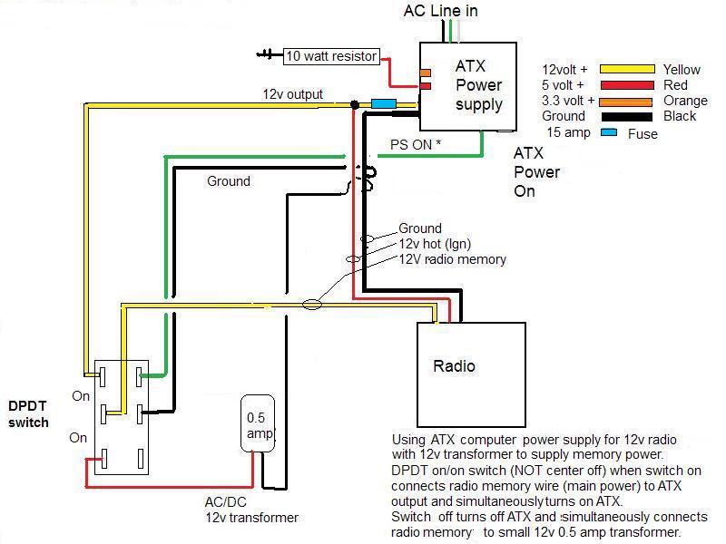
Utilizing a DPDT ON/ON switch.Switch turns on/off power supply and at same time selects 12v source sent to radio. When switched on power is fed to radio memory and ignition wires from ATX and simultaneously disconnects the plug in transformer. When switched off ATX is turned off, no power goes to radios ignition wire. At the same time it switches source to radios memory wire from the ATX to the plug in transformer-keeping memory alive....That's the short story..
Now the long...
Mostly because I wanted radio that I could run an antenna outside decided to use an old AmFm CD radio I have. Brand new 2008 Jensen that was in use for maybe 6 months before I sold truck it was in. Lots of reason but many of us just end up with a collection of old stereo stuff. I also had some new Pioneer 4 1/2" speakers that have to be at least 10 years old. They were bought for something but didn't get used. Also a pair of 6 1/2" pioneer that had never been unboxed. I don't even know where they came from- been moving around for years.
Point being, I have enough collected stuff, except a means to power, to scab together system for shop.
Which leads to the whole reason for this page...
Converting an old power supply (basically just cleaning up unneeded wires & plugs) to use as 12v power for radio- there are a bazzillion YOUTUBE videos etc describing that and NOT why Im putting up this page. The reason for this is documenting the addition of a 'wall wart' to keep memory alive.
In all the "how tos" I watched and read, though it was mentioned several times, I did not see one answer or means to address lack of radio memory power. Typically when using converted CPS for 12v, you tie the radios red(ignition) and yellow (memory) wires together and connect to power supply, which works. However when switching off the power supply, you lose radio memory. I also assumed like most I could live with that in shop but after a few days resetting up fader/stations, EQ etc, it got to be a pain. So began the quest for memory power.
Not sure how/why but it became obvious to me a simple plug in wall transformer 'wall wart' would more than supply enough power to keep memory alive. Just happen to have a few old 12v wall warts with various amp outputs. All I needed to do was figure out a way to switch between ATX power and the wall wart.
My first attempt, Fail, was using a 5 pin On/On relay..(relay w/2 #87 pins wont work)
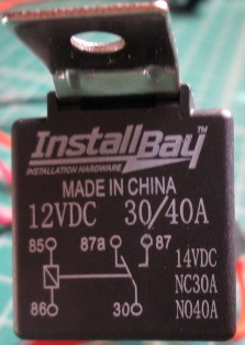
# 30 went to radio ignition and memory wires,
87A (normally closed) went to wall wart,
87 went to ATX with a jumper to 85,
86 ground.
When ATX turned on sent signal to relay #87 & 85 energizing really connecting radio #30 to ATX power #87, when ATX turned off relay closes and reconnects #30 to #87a power to wall wart.
Which worked bitchen as far as switching, however the time it took for ATX to bleed down enough to de-energize relay and switch to wall wart power left a very brief period no power, enough to dump memory on radio I'm using.
Some radios will retain power for a bit and keep memory for a few seconds so relay 'may' work.
Second attempt, Pass but really not practical. I then tried a manual switch between #87 & 85 to control relay for instant switching, which worked great, other than having to play with 2 switches. Manually turn off relay (engaging wall wart)
then turn off power supply. Turning on had to turn on power supply before tuning on relay-needless to say I dumped memory about every other time flicking wrong switch first.
Finally realized I could use a DPDT On/On switch, get rid of the relay. It would simultaneously turn on/off ATX and switch between 12v sources. So simple Im just amazed, And again the reason for this page. Using an old plug in wall transformer with a DPDT on/on switch.
So simple Im just amazed, And again the reason for this page. Using an old plug in wall transformer with a DPDT on/on switch you can turn on/off power supply and still have power for radio memory. I can find no one else has done this. Admittedly I had to buy switch so my system cost climbed to $6.
Wiring details at bottom of page but since Im here...outlining my system. Also making some observations in the lack of details in many of the how to videos.
Again not reinventing the wheel and describing details of converting computer power supply, pretty simple. But many of the videos folks are minimizing what they need to do-watch enough doesn't take long to figure out who knows what they are doing and understanding what's involved. You don't have to get fancy and use binding posts, solder all joints, not building a 32 roadster & make everything super sanitary... but I've seen a few scary 'shortcuts'.
• NUMBER ONE, in case the videos you happen to watch do not mention --IF the ATX has recently been plugged in, the capacitors (big round thingies) inside retain a LOT of voltage and can seriously hurt you, and in some instances can kill-period. Also most ATX when the case is opened there is a lot of exposed AC line components/wire exposed Pretty much impossible to work on without touching something you'll wish you hadn't, whether getting dead-shorting a component- don't work on ATX plugged in. Pay attention, don't be stupid, don't assume-
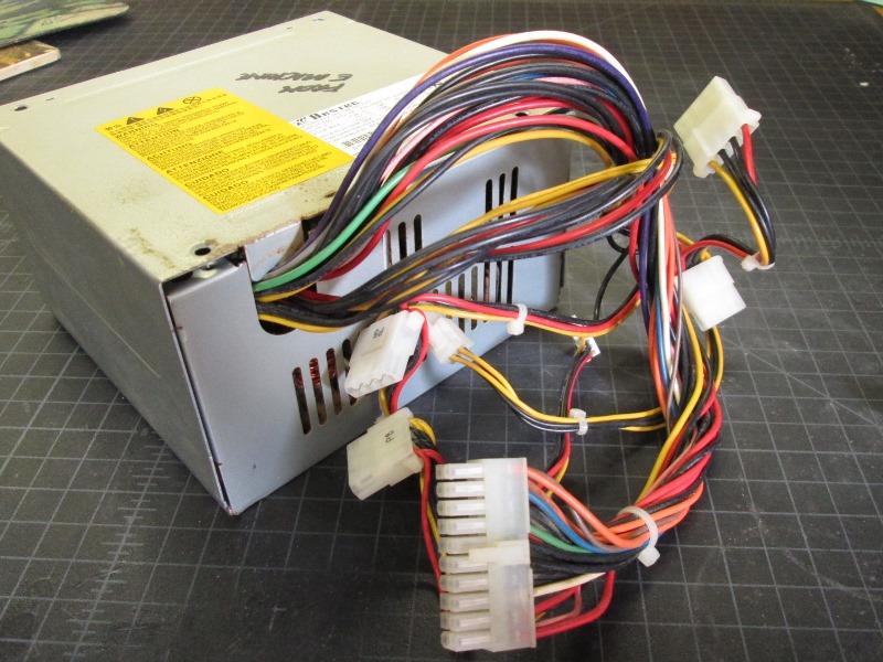
Besides lack of knowledge: Primarily its cutting and gathering all the wires. If your power supply can put out 15-20 amps on the +12V rail, its thru all the wires. Some will grab one of the dozen or so wires and pull full load thru a single 18ga wire. makes no sense.
• Gather all like colors (yellow is 12v) and run to output. The red 5v wires and orange 3v wires likely wont be using, though can be used to power LEDS etc if getting fancy. Point is if NOT using the 5v & 3v wires they still should be bundled together and isolated. The black ground wires are the only ones that you do not need all of them (especially if not using the red or orange wires). Just match, at minimum, number of ground to number of 12v hot wires used. Add extra for other hot leads you might add. (I added couple of extras to the main ground bundle, I also ran couple of extra loose ground wires to utilize for future use (ie radio antenna booster etc) and one to connect to wall warts ground lead.
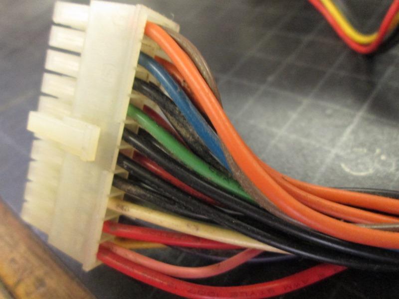
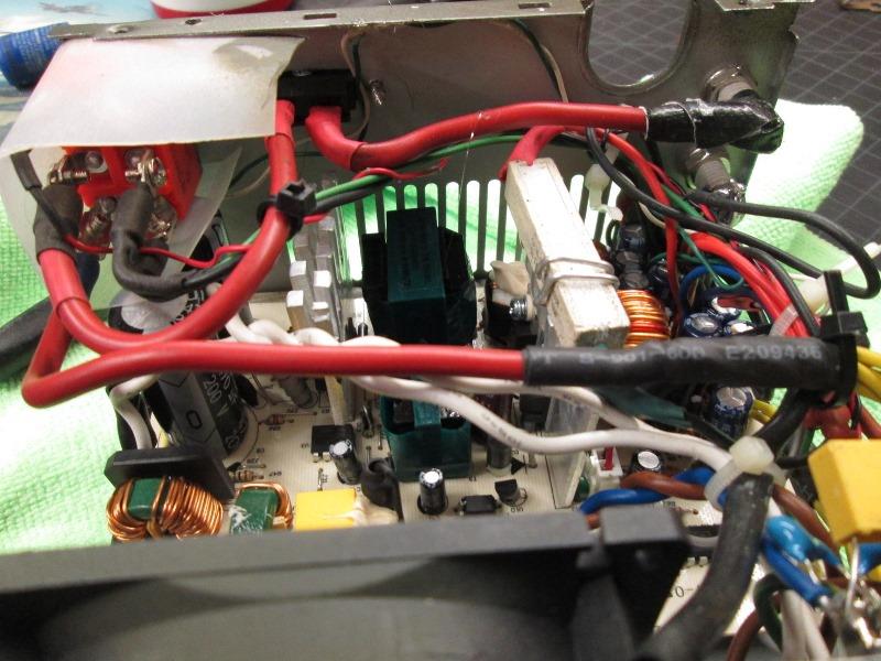
• Second is the main plug- LOOK at it before hacking wires. NOTE any wires that go into same pins. On the one above there is a brown wire tied to an orange wire. It needs to be reconnected to the orange wires. This one there is also a pink wire to red wire, again is must be reconnected to the red wires. These are sense wires, even though no longer tied to motherboard there is still some feedback to power supply for regulation.
The green and one of the blacks is what you should use to turn on/off power supply. You can use the main line-in case switch if your ATX has one (and NOT adding memory power) but using the green wire as on/off leaves the ATX in standby (just like the computer it came out of that was plugged in 24/7). NOTE you MUST use the green and black wire to turn on/off if setting up with memory power source.
This is a standard ATX plug in configuration and colors. Some manufactures (older Compac, some Dells) use non standard colors and pin wiring. Good luck with those...
	FYI color function
   	Black: Ground
	Yellow: +12V
    	Red: +5V  *
	Pink: +5v sense (if present connect to red)
    	Orange: +3.3V  *
	Brown +3.3v sense (if present connect to orange)
   	White: -5V  *
    	Blue: -12V. *
    	Gray: power on indicator.  *
    	Purple: +5V standby power output   * (Could be used for ATX in standby indicator pilot, non critical USB charging)
	       * (not needed/used for radio power supply, isolate)
• Third is READ the label on ATX case. Regardless of watts listed, which is the total capacity of all voltage rails, you specifically want to look at the amp output of the +12v ATX. It should be close to expected draw- or close to radios fuse. You can error slightly lower unless radio has an amp and you plan on using cranked to max. • Fourth DO NOT connect or use the -12v as a ground for 12v radio. That will give you 24volts! If using the 5v and/or 3v same issue. The minus voltage wires are NOT grounds. Only use the black ground wires for ground. [FYI if your building a variable low voltage bench power supply unit there are reasons to use the different voltages available-HOWEVER not to power a radio]
• Lastly some videos mention, some don't- test the 12v output with and without something (car brake light bulb, 10 watt resistor etc) connected to a red 5v wire and ground. Some units require a load on the 5v to get 12v up to stable output. Some, not common, but will simply immediately shut off if no load seen. Mine was 11.3v without load, 11.9 with so used a 10 watt resistor.
Too many good videos for me to duplicate-just spend an hour watching as many as you can till it appears clear.
So you can modify/use ATX to power your radio, connecting the red and yellow wires from radio to ATX for power (but no memory). Run radio ground to ATX
. Or a bit more to add memory power: Wire in a DPDT on/on switch between ATX 12v out and radios yellow memory wire. Add AC/DC plug in wall transformer, its positive lead also goes to switch. Radios red and yellow wires ARE NOT tied together. The red wire is connected to ATX 12v output.
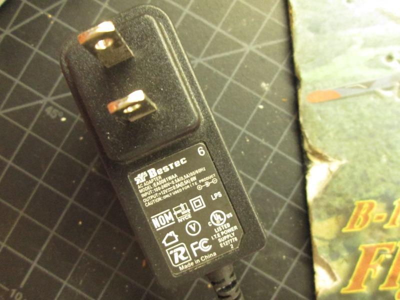
Wall wart: Any AC to DC 12volt transformer will work, 0.5 to couple of amps. At minimum I think 1/2 an amp, I used a .500ma, If it dumps I have another 12v@1amp I will use. If you don't save old wall warts, Radio shack sometimes has box full of take outs/ used cheap. New can also be had cheap. If hard wiring, test, but standard is center pin is positive, the wires, positive lead is marked with continuous dashed line.
Switch. Must be a ON/ON 6 pin switch. An On/Off/On switch will NOT work.
3 pins on one side of switch: Run a black ground from ATX to the center pin, run the green wire from ATX directly above or below the center pin, the other pin is blank. This side of switch turns on/off ATX.
THIS IS CRITICAL-
To the other row of 3 pins: connect wire to center pin that will go to radios yellow wire.
Connect the12v output of ATX to terminal OPPOSITE the pin the green wire is connected to.
Connect the positive lead from wall wart AC/DC transformer OPPOSITE the blank pin.
Run wall wart negative wire to an ATX ground wire.
This side of switch selects power source to radio-either from wall wart or from ATX. The radios red wire is run directly to the 12v output of ATX. When ATX off, red wire (Ign) receives no power so cant turn on radio when powered by wall wart.
When done switches center pins, one will be ground from ATX, the other center pin goes to radios memory wire.
2 terminals at one end, one will have green ATX on wire, the other side yellow (12v from ATX)
2 pins at other end, one will be blank and one will have positive lead from wall wart.
Clear as mud...but it works
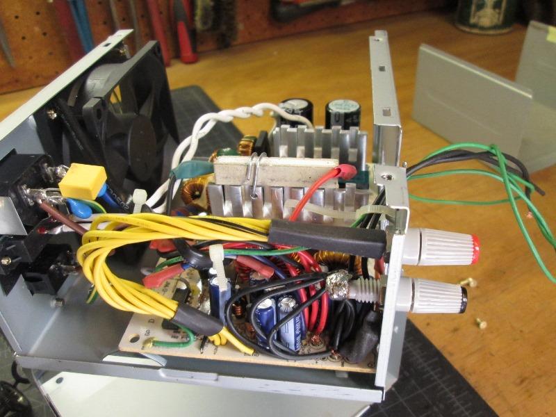
This is another unit I'm building, similar to mine except switch mounted to case, and few extras. Mine, switch is remote, transformer hard wired to radio and switch, Ign wire hardwired. But basically same, this on will set on workbench so tidied up a bit.
I've built 2 of these utilizing the memory option. Works well. The DPDT switch can be mounted to the ATX case or remotely. One Im using for shop radio has a remote switch because ATX not really accessible under shelf ( or if you were building a 'boom box"). The other unit has switch on case and intended to sit on workbench.Though I used screw terminals switch so if needed, wires could easily be extended and switch mounted remotely
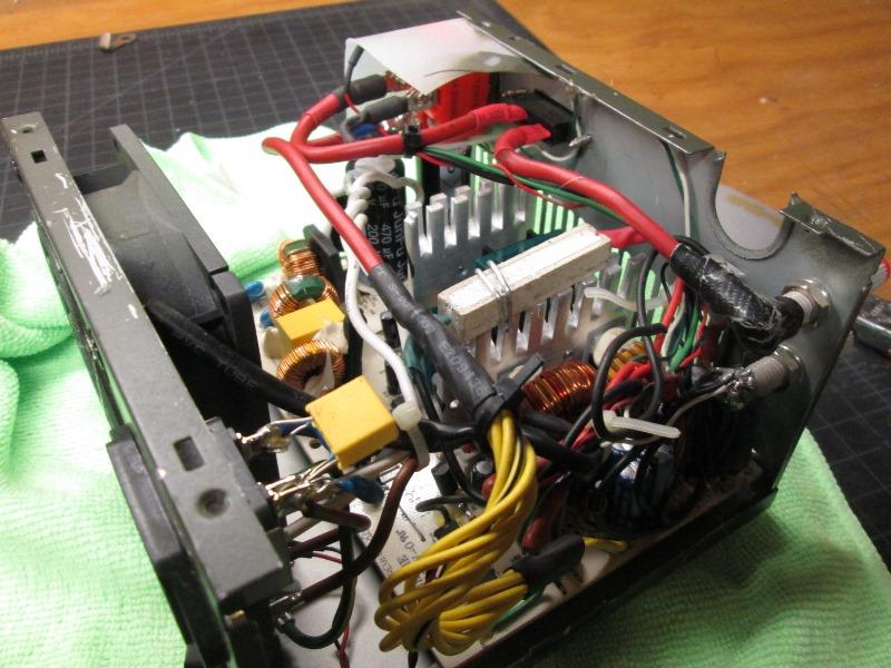
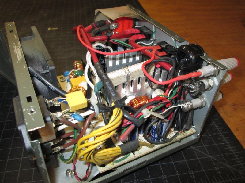
This, retro fitting second unit to utilize memory option. Already set up to run radio with all the yellow 12v wires and grounds routed to binding posts. Obviously binding posts not required. Green and black wire pulled aside for switch. Shown is the 10 watt resistor on top of heat sink added on 5v wire rail. On this unit added resistor increases and stabilizes the 12v output.
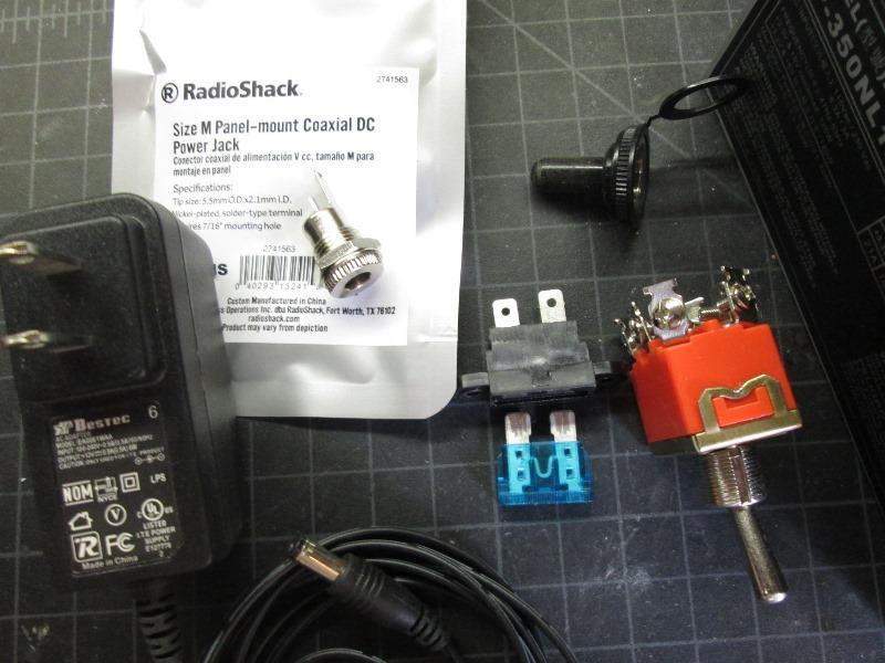
Parts required to convert to memory supplied ATX. 12v AC/DC transformer 'wall wart' on the left and a 6pin DPDT ON/ON switch shown on right. Fuse optional as is the receptacle to plug in transformer- it can be hard wired.
Here the 12v wires pulled from binding post. Soldered on length of 10 gauge and ran to added switch. From switch to fuse and then back to binding post. Ran the positive lead from wall transformer receptacle (the tiny red wire) to switch terminal above wire to radio. Connected the green and a black ground to the other poles.
Just another view showing wires
Last, added second output binding post and separate fuse. This is for the radios IGN wire. It runs and connected to the same terminal ATX 12v in to switch is on. Supplies 12 to IGN wire when ATX switched on, its before switch so doesn't receive power when switch turned off. This could be connected anywhere on the ATX 12v output before switch. Not un soldering the bundled yellow wires but could have gone to that. Fuses optional.
So easy enough to add memory if so inclined. May be others that came up with a simple means.
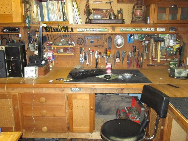
My radio...
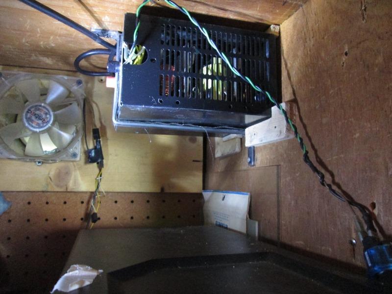
Radio is mounted to face board of shelf so the power supply is hung behind it from shelf. This was before adding the memory option and green/black wire were run to front switch that only turned on/off ATX. Radios red (ign) and yellow (memory/main power) wires tied together and feed by ATX. Worked just had to reset radio when power turned on-no memory,
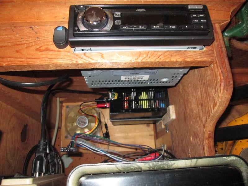
Radio cut into shelf face board, its an old Jensen. Its mounting sleeve is attached to board so I can still slide radio in and out. Not shown but used a simple L bracket with enlarged hole so when radio slid in its rear support pin slides into and supports radio.
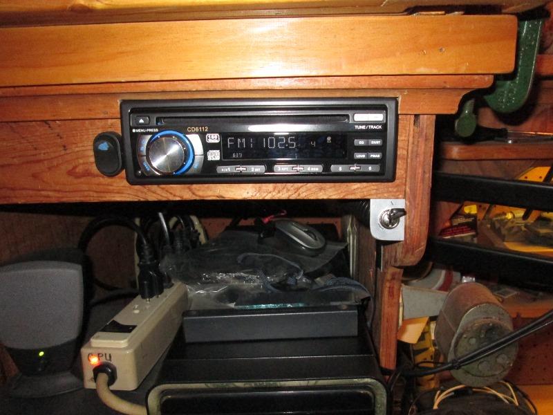
This is after adding the memory option and new DPDT switch. Old switch to the left Ill use to turn off ant booster I may add or something... Couldn't rework the counter bore on rear of face board to accept larger new switch so just left old one. Mounted new switch to aluminum bracket. Radios red ign wire goes directly to atx. The new switch is on yellow wire to radio- it selects where radio gets power, from ATX or wall wart.The green and black wires(ATX turn on) moved to new switch.
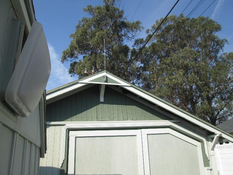
This was, other than utilizing all the equipment I had, main reason-getting an outside antenna up as high as possible. Didn't work as much as I hoped but huge improvement. Trying a taller loaded mast and likely a booster on wire but its consistent in reception as it is-just could be better.
Speakers:
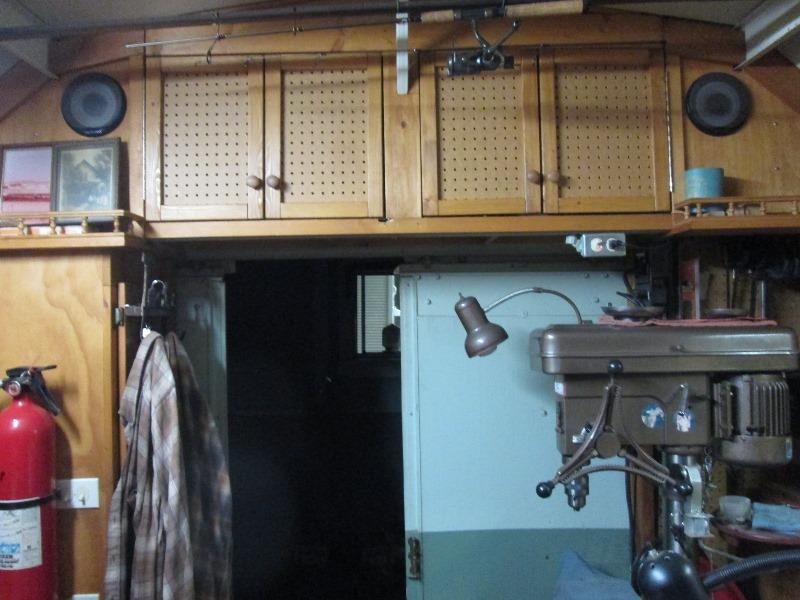
Rear 6 1/2" coaxial I mounted in upper cabinets. Ended up building boxes.
Cant really see after the fact, boxes improve sound but also to protect exposed speakers. Shallow at 3 1/2" deep x10"x 14" tall. Did seriously increase bass quality.
Front speakers:
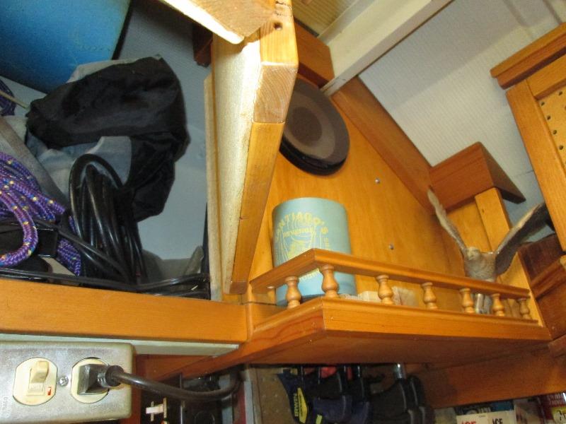
Not really a good place to put so I opted to put under the shelf at both ends above section of workbench used as 'desk'.
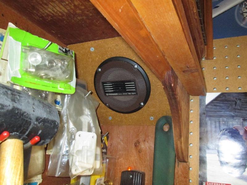
To simplify and not build more boxes just cut a board at 45° to use space at ends of shelf. Surprisingly these little 4 1/2" sound awesome. I don't know if its the internal shape or sound reacting with the shelf but the clarity, stereo separation & response is amazing. That and rear speakers point at front some of their sound is captured and mixing. Almost like surround sound-shear luck I wasn't expecting much. Coarse I've been listening to a cheap portable for years. Sounds better than my truck.
That s my tunes...
Old car radio, bunch of unused speakers, converted computer power supply, a plug in 12v 1/2amp transformer and a On/On DPDT switch. Power for radio and memory when power shut off.
Made a couple of messy videos because I found, as mentioned, no others outlining how to add memory using an ATX as power supply for radio.
Part 1-1st video- https://youtu.be/J11jwL3wNwk bumbling along till I got it. Really not worth posting or watching but process of how we got here-a radio powered by ATX that retains memory-
Part 2 of 3: https://youtu.be/x_coXUwgPrg Shop radio working w/memory, switching on & off. Started retro fitting memory option on 2nd unit
Part 3 of 3: https://youtu.be/4J19_bqYBIs Finished retro fit of 2nd ATX power supply
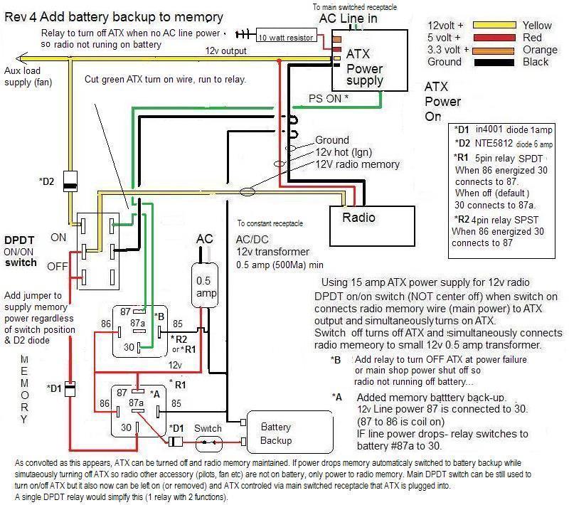
Update 2020: https://youtu.be/vxnpLxyfo6w Added 2 relays; 1 switches radio memory to 9v battery if shop power drops (or I forget to flick switch powering memory with transformer). Happened just to many times forgetting to switch before shutting down shop or line power drops...
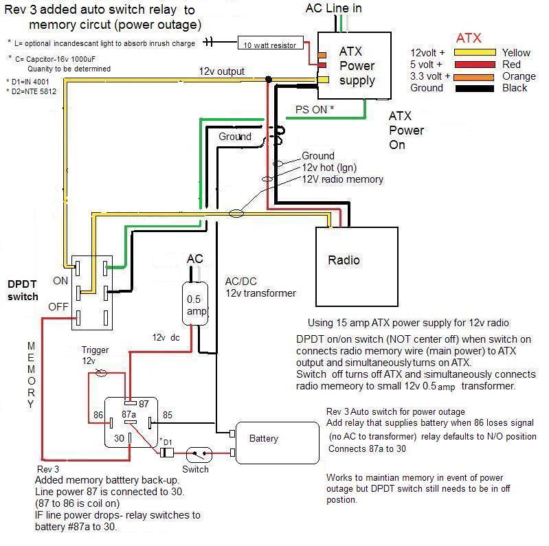
Second relay turns off the ATX if power drops so nothing but radio memory is on battery.
one thing leads to another...
Moving to separate page but ended up rewiring good part of shop. Started out running a pair of wires all the way to front of shop for the transformer to plug in that wasn't turned off at night for radios memory. Which worked keeping memory alive when ATX and rest of shop shut off. Discovered though this ATX power supply needs to be plugged in a while(standby) before radio is turned on. Turning on power to ATX, turning it and radio on (disconnecting wall wart) before it 'charges' it would shut off, dumping memory as wall wart no longer connected. So ran a un switched hot lead to plug. From there it cascaded...
All power in shop is controlled by 2 switches. Primarily started by adding an unswitched hot line to keep power supply in standby, be nice to have computer off switched line. Also there's a plug that's used for trucks trickle charger-when used i have to leave entire shop energized so be nice if it were on that separate feed. Few gotchas, the plug that power supply is plugged into there is several other things plugged in that don't need or want hot. Second the branch that feeds truck charger plug also feed couple of lights. Ended up twice as much stuff hot when main shop kill switch turned off...Some rethinking required
At same time I added another plug on separate 20 amp line to move electric heater to off the 15 amp line. Next morning coming out to shop noted the heaters indicator light is on...hmmm. If the heaters switch were left on means it could have run all night- Relying on memory to turn off or unplug isn't an option. Sometimes and or nightly just need to turn off a switch and walk out the door- That's why I had ran everything thru switches, I had defeated the 20 amp circuit kill switch some time ago when I add exterior motion sensor light and circuit had to say on. So need to move light onto unswitched line.
Radio was final straw, but additions and changes in shop finally at point need to readdress wiring. shop rewire
Back to top of this page
Back to Our shops tool mods section