Convert Dually fender marker lights to blink
- Sections on this page..
- 1st main project is simply convert fenders light to flash with signals Tied in both mirror lights so all lights at sides of truck flash the same.
- Original install was non powered converter-changed to a powered unit but other than addition of battery power wiring unchanged
- Add park light power manual switch to turn off park to converter Signals thru converter flash opposite of truck when park on, switch makes them flash in unison. Primarily for Hazard light use.
- Remove "key in ignition" chime ground pin Not part of this except I broke mount and chime would sound on its own.
- Video of initial fender/mirror lights working
- Updates: add manual switch to power non flashing lights when manual park switched & used with signal. This is when converter was replaced
- Add front fender marker/signal lights SO signaling intent can be seen from side of truck. Add running lights to rear bumper, swap front turn signals to LED w/ electronic flasher (UPDATE: 10 months later flasher failed- change back to resistors)
- Replace backup bulbs with LED rewire added bumper lights tieing to fender lights so they now blink
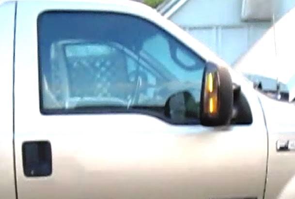
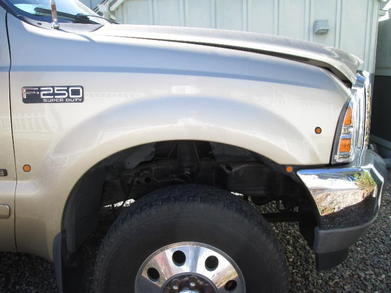
Old picture but I've always thought marker lights on fenders should blink with signals. Making a single wire/filament bulb to display running light and blink with signal takes a bit of effort. Simplest is to move the ground wire from non blinking running light and attach to hot wire of a lamp that blinks. Will flash opposite of other signals. There are many other methods using relays or diodes etc but gets a bit, well, high in component count and result often is same, signals blink alternate. I assume anyone reading this is looking for a solution.
My search led to using a 3 wire to 2 wire tailer converter. I think it will accomplish what I want. One component to install that will feed running light power and blink in unison with signals.So that's what were trying.
Parts is parts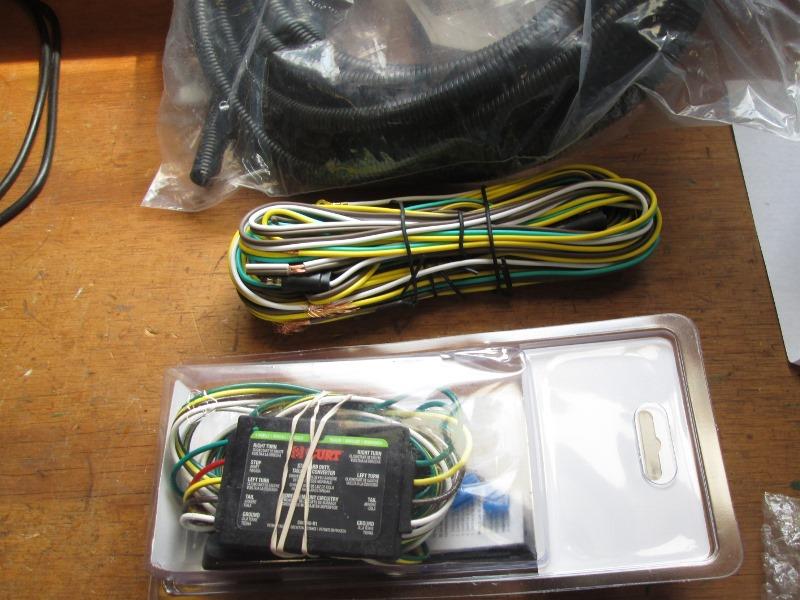
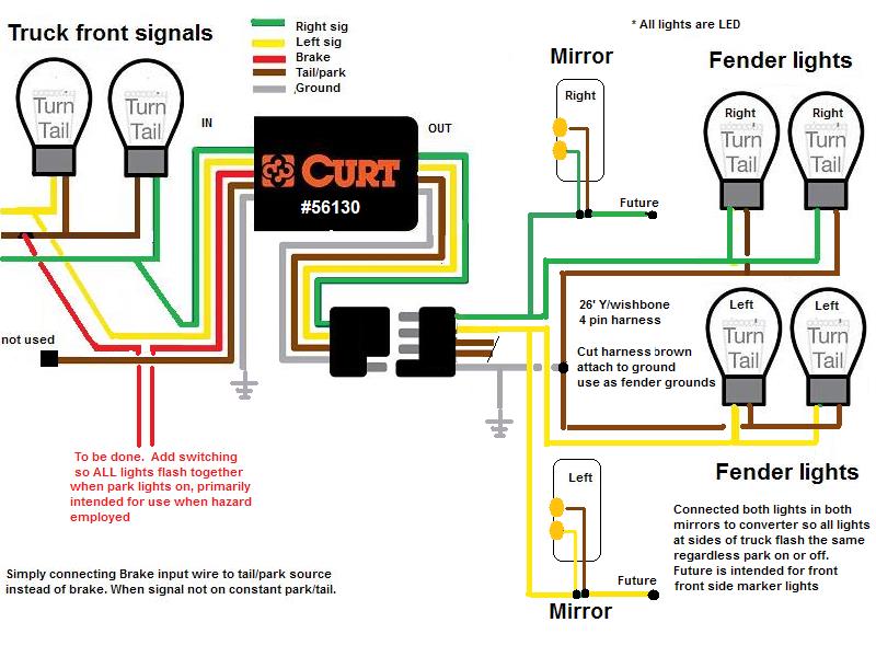
Converter Curt 56130 56187, 25 Foot 4 Wire 4- Wishbone-Style (2 running light wires) and 26' of 3/8 loom.
There are many converters, confusing. I chose a Curt 56130 , non powered unit. (ended with a #56187 powered unit because i blew up first one). Mostly for price $20, the lights Im using are LED (some wont work with LEDS), so I dont see need for a powered unit.
The Curt 59236 unit is sealed, could be mounted anywhere but 3x the cost. The idea is converter takes multiple inputs, sends to light on same wire. Designed for vehicle that has separate brake, tail and signal bulbs, combines and to sent to light that has only 1 bulb/2 filaments yet retains functions.
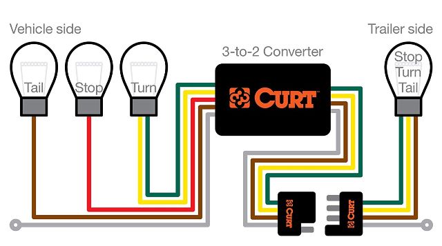
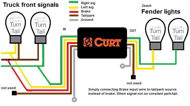
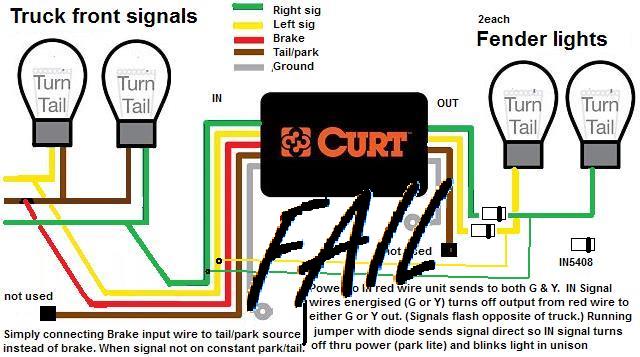
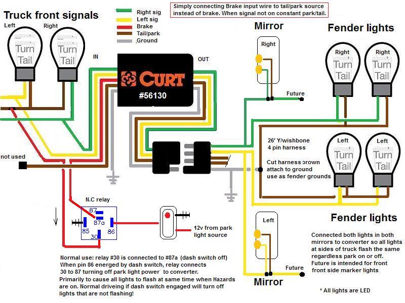
Specifically it combines the stop and signal and cancels stop light input when signal on. What I dont know at this point if this Curt unit flashes in unison or alternate of signal like a relay that uses hot signal to turn off light. (Note diagram shows both left/yellow and right/green but in use only 1 is used depending on which side of truck. Light grounds not shown)
How we are using, taking input from 2 sources (park and signal) and sending to single filament bulb. Not using the brown tail thru put, connecting tail/park to the stop input.
Hoping this works, I've read others have done but unknown if its the manufacture or particular unit that allows signals to flash in unison.
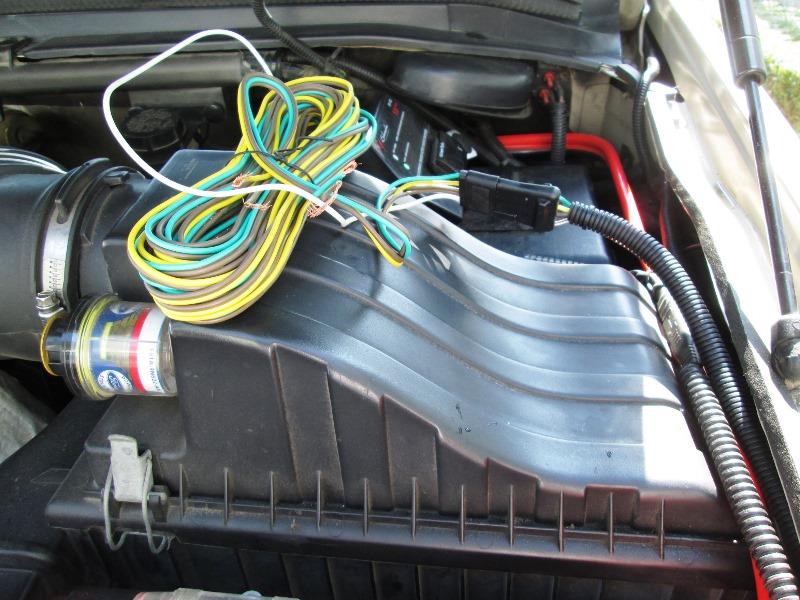
Our trucks fender lights were connected to rear taillights. So quite a bit of rewiring to disconnect and reroute so leads face front of truck. Im connecting converter to the front signals to keep the brake light out of circuit. I have a front hitch and light receptacle (for scooter rack) so will make my connections there. Install the converter somewhere in engine bay then run wires to fender lights.
First is testing unit to see if it will actually work. Confident it will but its seeing whether flashing with or opposite other lights. At this point doesn't matter but really dont like the alternate flashing lights.
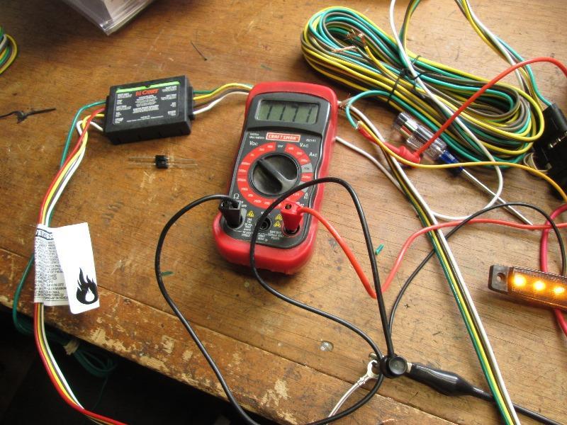
Welp---unit simply uses signal power to turn OFF power from red wire to that side. So signals flash opposite of truck when park lights on, normal if park off. Dang it..
- You can jump thru this section-Skip didn't work. Thought I had easy work around for alternately flashing lights
Realized though running jumpers from signal input direct to light, bypassing unit does work. When signal turned on, left or right, unit turns off thru power to that light. By passing feeds direct signal source to light, Yea! Lights sync.
Diodes to stop feed back but dont know if unit cares. So turning on a signal, unit turns off output, lights flash with truck. Signal turned off, thru put of red wire (park/tail) restored. Cool.
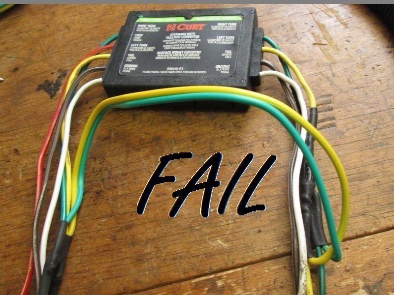
- Installed and FAIL...
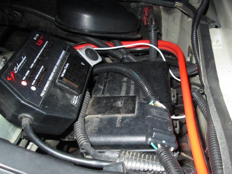
NO clue, signals work (may be due to diodes bypassing) but power thru for park light is at about half voltage, 6-7 volts out, 12 to 13 volts in?. Not enough to power park lights. Unit gets very hot. Because I have by-pass diodes on signal leads cant test thru voltage for signals power thru unit. Checking everything appears voltage drop is half. I'll cut diodes to see if it works but likely at this point get to remove unit take back to shop, where it was working. Cant image with blocking diodes what caused failure.
Although I did note better than 1 volt voltage drop when originally testing, it worked. I've already ordered a replacement unit in case this one is dead. Same unit but powered, so hopefully address the voltage drop. In stock form the alternate flash still an issue. I suppose instead of using diodes is let it work as designed.
EUREKA! Well it was my diodes. Converter good.(so I thought-failed later) I placed on output so direct signal bypass wouldn't back feed converter. Cutting out to test converter lights came on? Testing, what I figured out is diodes stopped back feed to the out put of controller, but it created a loop where the output (park light power) was able to get to input via the by pass back into input. clear as mud.
Now the bad news- light flash as normal daytime, when park lights turned on flashes opposite of truck. I tried everything under the sun I could think of, relay, relays diodes/-nothing or created new issue. Problem its the single feed (stop) for both lights. Unless at night, I cant live with it or have a real need for lights in unison, an on/off switch for the park lights power would work. Kills opposite fender but say I was along side of hi way, side toward road all flashing at once would be nice and more visible than alternately flashing lights. Right now Im done with the controller, installing as stock. Left the leads on output side as they could be used if I add front side mark lights.
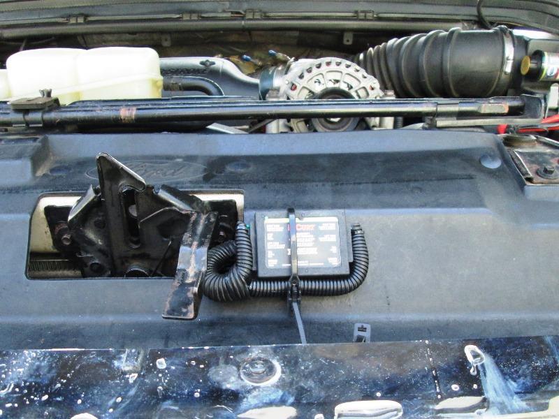
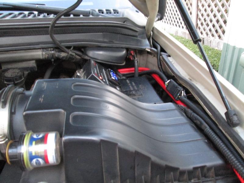
Mounted converter on top behind grill. Hokey but easy access to wire, semi protected location. Attached with reusable zip tie, it easily could be moved behind out of site. A lot of looming, solder and zip ties. I tapped 4pin hitch receptacle on bumper directly below. Output goes across to fender then back ending at firewall with 4pin plug. A 4pin extension will be plugged in here, drop down and run to rear fenders. That should be fun...
Button up engine bay. All I need to do is plug in the extension and run to lights. Maybe go back to address alt flashing lights.
Ready to run to fenders. Extension I'm using has separate running light wires (Y style harness) for left/right.
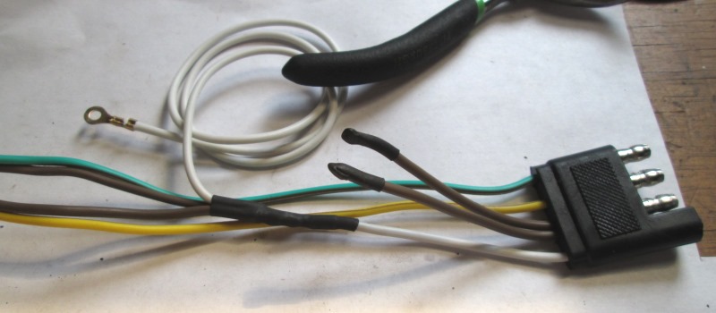
Cut the brown wires at plug and solder to white ground wire to run to fender lights and use as grounds as I need to ground fender lights and not have do under truck. Ground end of white wire to truck. Converter has ground on input side so will be grounded twice but also grounds lights. Left brown stubs that 'could' be used.
Also when I run the extension to fenders I'm adding tap wires on G/Y just before door. Primarily is to run wire for mirrors and rewire mirrors so that both their 2 lights are powered as park and signal from converter. Currently mirror 2 bulbs are separate functions and visually oriented different, IE cant see signal from back, cant see running light from rear. Tieing together just more visibility and see both functions from any angle. But main reason to rewire mirrors is to minimize the alternate flashing lights. They would flash with fender lights so all lights on sides of truck flash together. Also I may add side markers behind front fenders later, matching lights on fenders. Allowance so I dont have to get back into loom for whatever I do.
Hmm further thought, solder Left/Right mirror leads near plug (dont need a ground). 2 wires inside thru firewall instead of up thru floor and back inside cab. If I add the front marker lights I can use a Y splitter or something later. Actually front lights if added would be at side kick panel inside cab-just tap the new mirror light wires inside cab...Wow just saved my self a whole bunch of work (and wire). A lot cleaner and dont have to do now.
Side track-Readdress recently added grill ID lights since I was here. Not part of this project but hooking up converter park light power it's now 6" away from ID light power lead. I had tied to cab light wiring but meant I had to switch on relay for them to work. Disconnect & remove previous wire that ran from under dash cab light relay to power grill ID lights. Ran grill light power from converter park light input that comes from front hitch receptacle. That takes care of any future need to modify should I reinstall cab ID lights. Also they now are tied to park lights and not run thru switched power for cab lights. Always on if park/headlights on.
With that done preceded to run extension. Realizing I do need to add the wires to feed mirrors now & at the same time so it can all be loomed. Easier to solder with extension free. It would be twice as hard doing later.
Saving myself a whole bunch of work took forever?
End of day, engine bay almost done...
So to the extension, about 6" from plug, solder 2 leads about 4' long that will power mirror lights. Ran the extension with extra leads down under truck. Actually I pushed the plug end up to engine bay. Underneath the new leads will split off, turn & enter boot to go inside cab while the extension will turn opposite to follow frame to fender lights. Once I had the wires ran down from above I pushed wire loom over all the wires until it reached boot. Then cut to length at plug. From below pulled out the extension where it will turn. Again from end of extension (20'+) pushed loom over until it reach new lead loom. Taped it making a Y. That took a least 2 hours.
In cab I secured the new leads up under dash that will attach to mirror leads eventually So pre wire into cab done almost. Once extension to fender lights connected I'll use excess wire (I'm sure ther will be quite a bit) and attach leads to the mirror wires long enough to reach back to kick plates at either side of floor for future access should I add other lights (front side markers).
The extension is loomed ready to run to fenders and solder to marker light leads. That shouldn't be to involved. But it got dark and Im done. Tomorrow reroute extension in engine bay to follow orange cable, zip tie the loom & plugs out of the way, kinda draped right now. Find a good place to attach ground. Its grounded at the converter end and thru plug but extra ground on extension always good and be direct for lights.
Once if fender lights work its back inside to rewire mirrors.
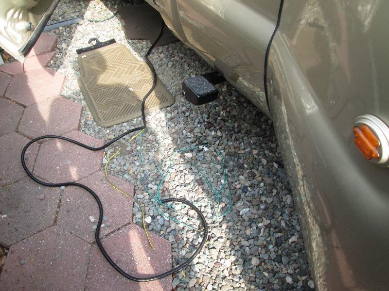
Running loomed wire to fenders just following existing cabling. Going to solder connections but crimp butt connectors sure would be a lot easier than laying on my back soldering over head...
4hours later. Rolling around the gravel soldering fender lights, shoving loom, bazillion zip ties trying to sanitize. Came out nice but a lot more work than imagined. Tested and fender lights work
Back inside to finish wiring mirrors.
Disconnect park and signal leads to mirrors, capped. Leads from mirrors tied together and solder to new leads from converter. Added short drop for future front marker lights. Likely be a while before I do that, if at all. I looked and the kick panels are not on the other side of location. Its inside fender but didn't look to see what would be required. Another project, maybe. But pre wired if I do.
Almost finished, everything connected. No pics, figured really only show in a video. Course I waited till sun went down but didn't adjust camera for low light so pretty fuzzy. First segment shows with park lights off, everything blinks together. Second shows with park lights on and fenders/mirrors blink alternately.
Tidy up engine bay
I am going to add a switch for ability to turn off park light power to converter so all lights blink in unison when wanted. When hazards on the alternately flash bugs me. I'm thinking a 5 pin relay so only one power wire from dash to trigger it. When energized it will switch off park power to converter, all lights will blink in unison. Place switch with a very annoying red pilot so not left on and driving with no fender or mirror marker lights.
All in all I think worthwhile. Really like the mirrors, both lights in mirror tied, signal or park a lot more visible, Wasn't part of the plan but glad I did. But seeing the fender marker lights blinking when signaling that was the real payoff. Just a personal thing I'm sure.
My wiring
Still contemplating the park light off switch. A simple on /off switch on park power to converter would work to make all lights flash in unison. But in normal driving when interrupting park power to converter it will also turn off the park lights (& mirror) on side that isn't flashing. Intent its to make all lights flash when hazard on so it would be better if the hazard button would actually trigger really to cut park power to converter. Be awesome IF I could determine a wire or terminal on hazard switch that triggers 4 way hazard to tap.
Other option is to place on/off switch near the hazard button... there's room.
More wires but doable and simpler than tapping existing switch. Grab ignition hot hot from park light to switch, then out to N.C. relay near converter. When really energized disconnects park power to converter. Switch/Relay off normal power to park restored.
Switching park power to converter
In less time I spent contemplating I just started hacking...
Mounted relay facing engine near converter. Its wiring is on other side.
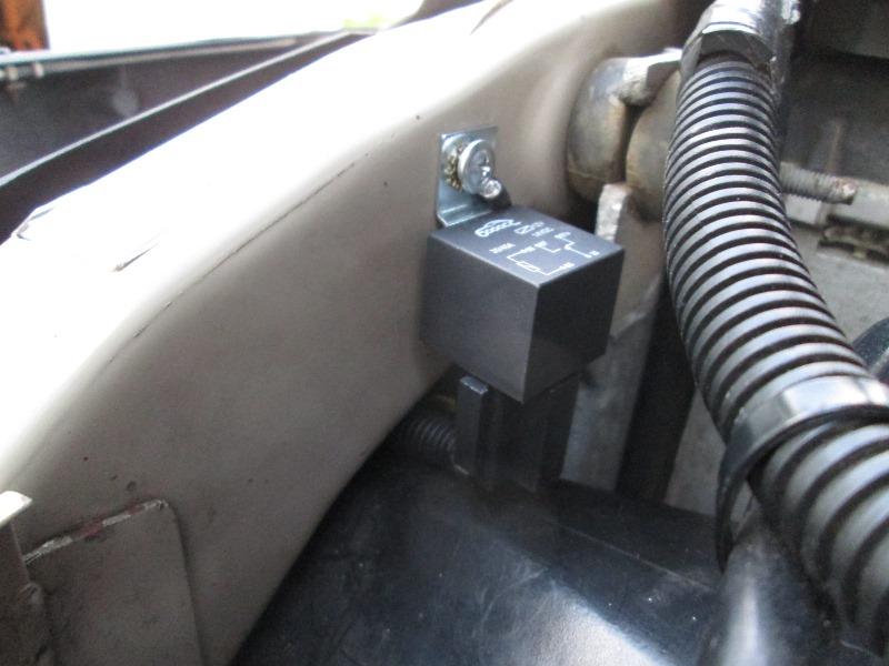
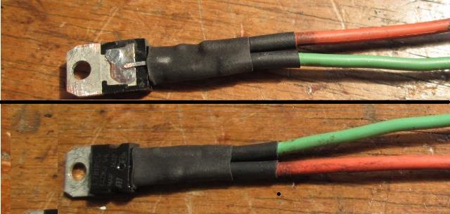
Basically splicing relay pins #30 & #87a of relay inline on park wire to converter
Cut the park wire source to converter and ran to relay pin #30
connect the other end that goes to converter to normally open pin #87a
Pin #87 not used.
Ground pin #86 at relay mount.
Connected pin #85 to end of power wire (from existing park power) that will go to on/off switch in cab.
Took almost an hour pushing trigger wire from relay thru existing looms into cab behind dash.
Removed the upper cowl on steering wheel column, install switch on top with red LED. About 1 1/2" to the side of Hazard button under cowl is open with plenty of room for a switch. Grounded inside for pilot.
The wire I just pushed up from relay pin #85 connected to load pin of switch
Power to switch is from existing relay that's hot when park lights on.
Reinstall steering wheel cowl
When considering power source for switch,2 things. No reason to use switch when parking lights are not on and 2nd, switch/relay can only be turned on if park lights (or more important relay is auto switched off when park lights off should I forget to turn off).
In normal driving park power goes thru relay pins 30 to 87a. When pin 85 energized relay switches #30 to #87 which disconnects pin 87a. Park power interrupted. All lights flash in unison when park/headlights on!. Again this wont be used for normal night driving because it kills the side that isn't flashing (fender & mirror) . Other than that, when someone talks smack about my alternately flashing lights simply hit the switch...
This primarily again is for use when hazards on or just the ability to control flashing sequence.
. Finished wiring with park interrupt.
Side track-
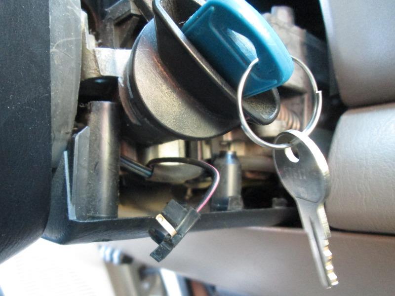
Not related to this project except when pulling the ignition switch to add the park light switch. Many years ago I broke the 'key in ignition' sender. Its a simple metal pin that when key is inserted it touches and grounds chime circuit. The little plastic clip that holds it in the ignition switch barrel broke. My fix was some tape to hold it. Worked for at least 10 years usually.
When I removed the switch for this project the tape that was holding it position fell out along with the pin. Thought I re taped but next day setting in the shop I kept hearing this faint chiming. Finally walked over to truck, yup, chiming away.
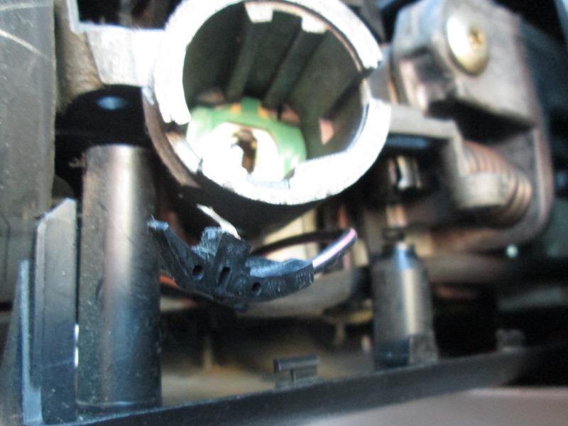
Opened up the tape had slipped off allowing the pin to ground.
My permanent fix- simple remove it from barrel. Wrap with tape sticky side out so as not to get glue on pin (should I ever decided i need it) then tape it and let it rest behind the column cover. Everything else still works, If I lock myself out of truck because a chime isn't reminding my, I'm an idiot. I just really dont need the chime, I need less for it to come loose and chime forever. 2nd reason is it only worked about half the time anyway, it doesn't always chime when key left in because it can move in slot.
.
Youtube video if embed doesn't show https://youtu.be/IowwM4mCshQ About 5 minuets...
UPdate:
2 updates actually, and converter replacement
I added a 3-way switch to be able to power left/right side fender lights when the manual park power switch was used for night time signaling. (cutting park power so lights flash in unison meant that side the wasn't flashing lights were off ).
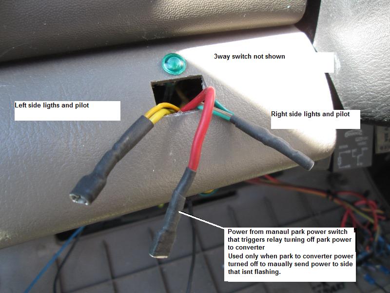
Though originally the park interrupt was to have EM/hazards lights all flash in unison, decided I wanted the ability to signal at night without killing opposite fender, why not. Added a pilot to indicate the manual power was engaged which required diodes to stop back feed left/right thru pilot and diodes to stop main power leads from triggering pilot lamp. Worked well, I can turn off park power to converter so all lights flash in unison and manually turn on park power to lights that are not flashing. This isn't a feature that would be used much, just wanted the option. However...
soon after adding this option Converter failed, though not due to this.
The 1st Curt unit Failed. I do not think problem with converter, I killed it, I'm pretty sure it was initial attempt at by-pass where it overheated caused it to finally fail. Then above addition caused diodes to fail. Then the right side signals stopped flashing when park lights turned on, then the left side did the same. So signals only worked when park is off. Second issue, the original diodes I placed on output were too small (3amp) and overheated and melted loom. I assume this occurred when manually sending park power to lights (and back at converter). Removed converter and bench tested and verified, no signal flash when park on (brake input wire). Toast.
Replaced with similar unit but its powered (#56187) verse the 1st one (#56130) that wasn't powered. New one uses same inputs to trigger function but sends battery power instead of just passing power from source.
I cut out old one and cut wires on new one (about 12") to match and solder all leads to previously run wires. So other than cutting out old one and installing new one, just ran new power wire thru fuse directly to battery. I didn't replace diodes on main outputs. Everything functions.
I likely will add diodes due to the manual park power sending power back at converter output but will use 6amp and see what happens. It may be converter doesn't care.
Only real 'yet to do' is changing the tied directly to battery power for converter, run thru a relay so its only hot when key on. I dont know if there's any drain when not activated but if hazards on for extended time, removing all the lights thru converter would be less load on battery increasing run time. Course if that were real issue could just pull the fuse.
Final wiring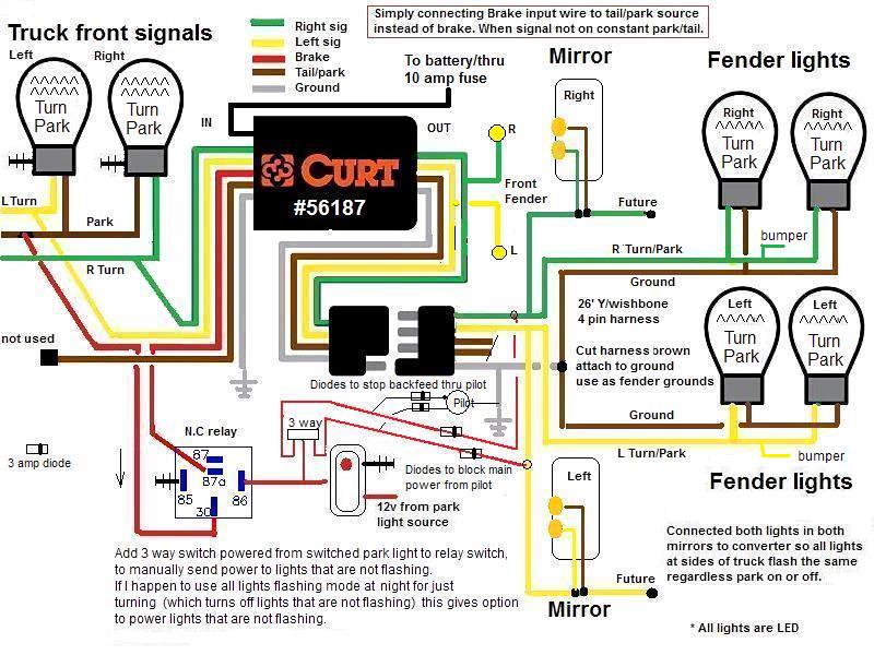
Done:-well other than leading to 2 new projects.
top of page
Convert front signals to LED, Add front fender lights
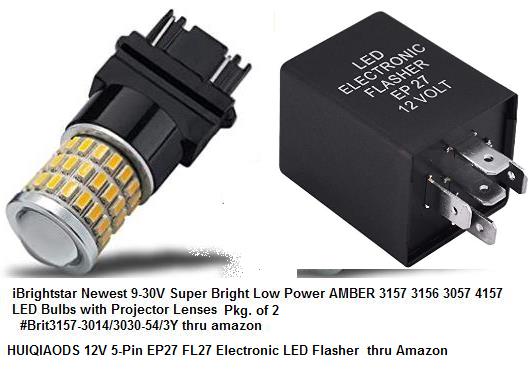
Changed front 3157 signals to LED. My rear taillights fixtures were previously swapped out to LED, they have resistors in line to stop hyper flashing. When I add front LEDs Im going to change Flasher to electronic and not use resistors in front. Remove the resistors in the rear. This will drop the amp load required considerably (4x 3157 incandescent).. , I've read a lot of folks having issues with the electronic flashers so prepared to add resistors back if needed. Hopefully the electronic flasher works. (it did for a while)
(Flasher fail 10 months later, going back to stock flasher with resistors)
Then flasher failed, install, fail and fix moved to separate page replace flasher with resistors
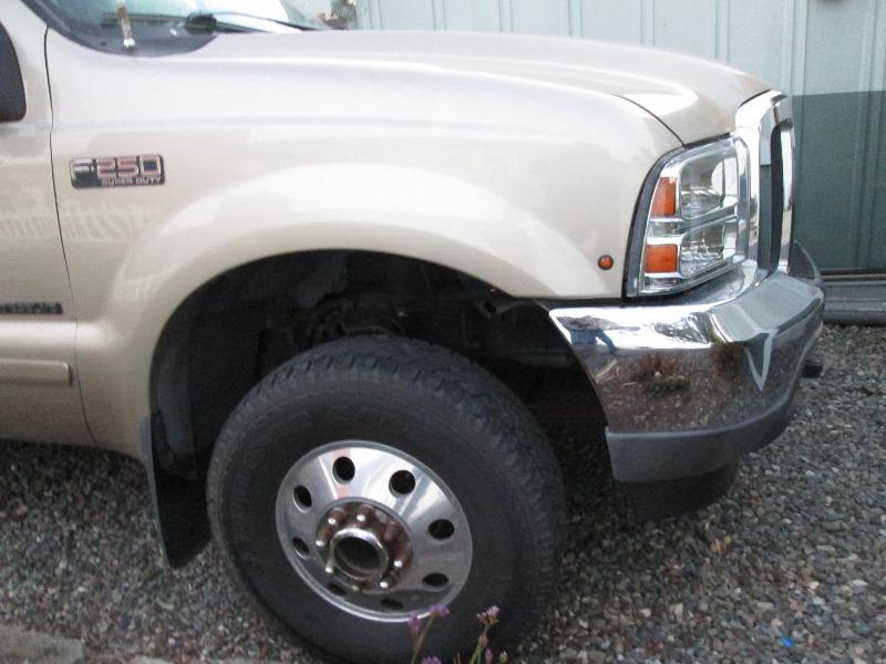
Second project is adding front fender marker lights. Now with the converter I can add front markers and have both park and signals. Something I've wanted to do since I converted headlights to '05 style a few years ago. The '05 lights, the side marker is recessed behind lens and cant really be seen well approaching from rear until almost beside them, signal cant be seen at all.
- And side markers
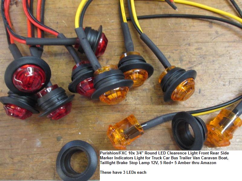
Small but VERY bright LEDs, pkg of 10 for $10. Small enough to place any where with 3/4" hole. Good thing because now in hand hesitant to drill holes in my body.
Drawing pictures...Originally I thought just in front of door like many, would also be at same height as rear fender lights. Be a bit difficult, some odd sheet metal, does seem a more 'expected' place. However leaning toward at front behind headlight at nose of fender, except for drilling body. Noted small area between fender and bumper. Would be good, make a bracket, no drilling required. Doctoring this picture to show options I saw if I place at bumper/fender one back in front of door would be in line....Doh. Also that smoke lens may have been better choice,
More thought required. On nose behind headlight is out. At fender gap for sure. Pulling the inner fender liner to see if doable in front of door. If possible then its thinking long and hard about drilling. All I've determined is wiring would be simple. Start from where flat plug is from converter, across firewall and dropping down. Left side would be straight down. TBD
As there isn't any real need for this, just kind a wanting to & something to do, may be awhile. IF I install I'm adding some drop down resistors. At 12+ volts these are intensely bright and drawing 1/2 watt and climbs as voltage increases. Also they have shrink tube and epoxy filled. But the shrink tube isn't 'shrunk', water can get inside thru the shrink tube past most of the epoxy?
And plan completely changed. Both location and wiring. Tried to make bracket but looked goofy. Ended up drilling the fender at about mid-height of headlight park lens so when lights are on inline with front park/signal lights. Nixed the one in front of door. Intent is simply when someone beside truck they can see signal. Drilled 1/4" hole then a 5/8, finishing with a 3/4" counter bore bit but not quite all the way so a little less than 3/4" hole. Cleaned up with mini file and painted with some Galv primer.
To the lights I pre wired lm7812 voltage regulators from positive leads. Install lights into holes. Grounded right behind headlights and attached pre wired regulators
When an LED doesn't state voltage range my assumption is on a vehicle, charge that may see 14.6 volts, LED will be over driven.
Ran power wire from regulators up to loom from converter and tapped into left/right wires.
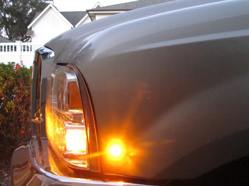
Dang! There still really bright. If they burn out I'll add resistor at replacement light to choke current.
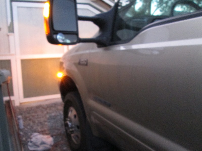 Bottom line is truck is quite visible, signals can be seen from any angle. My rear dually fender lights flash with signals (what started all this). Pretty happy so far...
Lastly I have old bumper bolts from previous happijac camper tie downs. They are at each end of rear bumper. I probably will remove, enlarge the hole and replace with 2 of the red LED marker lights like the front.
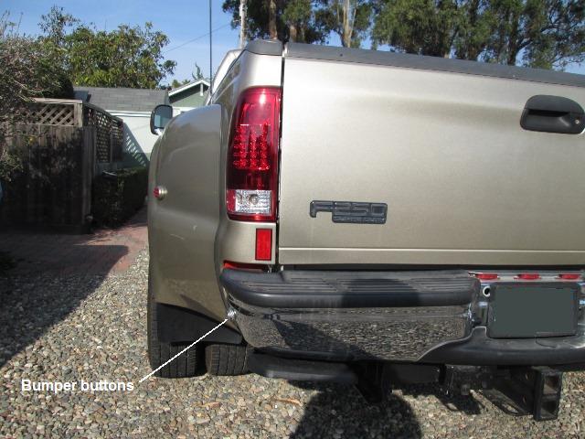
Debating though about tieing into all the other side lights off of converter. IF I had thought about this when I rewired fender lights I could have dropped wire for these. But I hadn't and getting back will be an effort. I 'think' 'Ill tie into the 3 ID light bar in the rear or drop a wire from taillights so they just act as marker and not flash. Actually thinking about it the original stubs for fender lights from taillights are still there. So I cold drop wire and tie to either running light or signal.
That's what I did, After removing the happijack bumper button, enlarged hole to not quite 3/4". Dropped wires from taillight park wire & ground. Left side done. Its tied to parking light but it's so bright when I add the right side adding resistor to decrease its intensity then redo this one.
Not sure I like this at all...committed at this point. Maybe after resistor added lowering brightness be ok, Could reroute to the fender so it blinks, though constant marker good thing its just too bright. Figure it out when I do right side...
Installed the right rear marker into bumper with added resistor, add resistor to left side. The 1/2 watt/270 ohm resistors do take the 'edge' off of light. Currently tied to taillights park lights. Wire on power leads are long enough so I 'could' reroute to fenders should I decide they should also blink. Still debating on that. Ones in front are tied to signals and park thru converter. Rears are to taillight park. If park not on and just the hazards the added bumper lights are not lit.
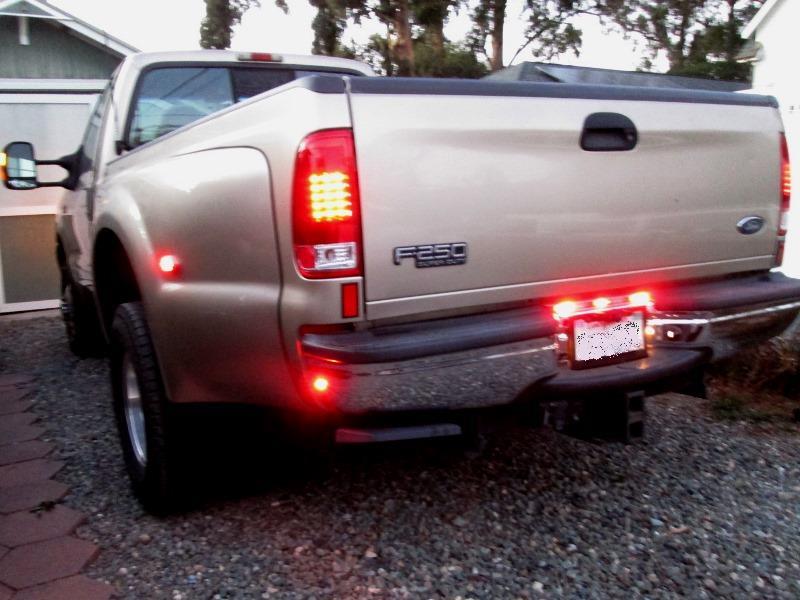
Tried to take video at night, showing all lights flashing with park lights on, new front & rear markers, but really doesn't show well...
.
Youtube video if embed doesn't show https://youtu.be/A6RbSudaYiY About 1 1/2 minuets...
Rewire bumper button lights, replace backup bulbs:
Welp bit the bullet, Having the bumper lights at full width and not blinking bugged me, so the added bumper lights come on with park lights and now blink with signals (or pulled the inner fender liners, removed taillights, cut the power wire to bumper lights reroute and connected to the rear fender lights, reinstall the fender liner). As fun as I imagined.
When I decided to connect rear bumper lights to fender lights, which meant removing taillights again, I ordered LED backup bulbs to replace the incandescent bulbs. Brighter and whiter but replaced more for the power freed up to drive camper sealed beam back up lights.
Except for the 2 front factory side marker lights in the headlights (all but worthless) all exterior marker and signal lights are now LED.
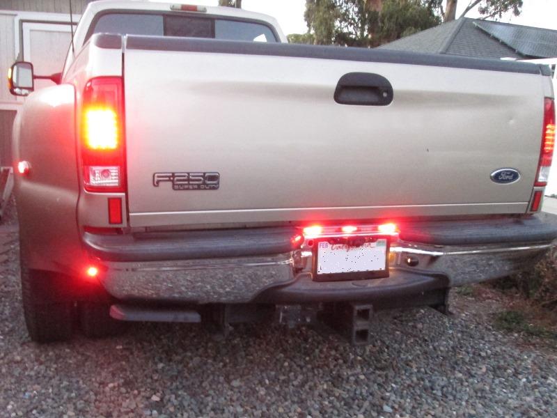
Last attempt night display of lights with bumper lights tied to fenders, new LED backup bulbs
Youtube video if embed doesn't show https://youtu.be/Nz5lBsVpIF0 About 1 1/2 minuets
top of page
Back to our F250 truck page
Back to Ourelkhorn Camper Modifications page