Repurpose microwave transformer for spot welder
- First is the transformer.
The only difficult part, removing the secondary windings. Some split transformer but I don't recommend. I cut outside loop of winding off and drove what remained inside out thru other end.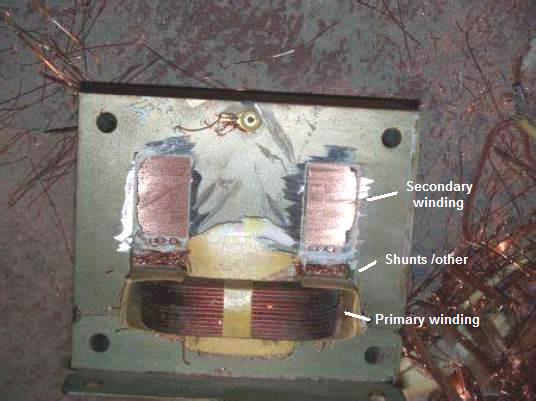
You can drill thru to help. This isn't mine but shows secondary (very fine wires) cut, This person also cut the shunts between primary and secondary which unneeded. Once secondary winding out any shunt or wire will come out. MAIN FOCUS here other than removing is NOT to cut/nick damage the primary winding or its coatings. Protect the primary windings!
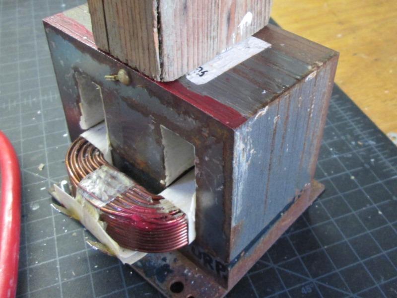
Mine with secondary windings finally removed.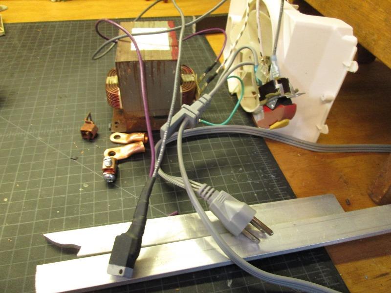
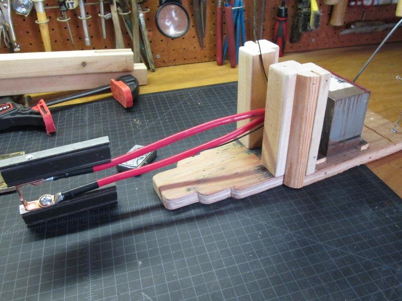
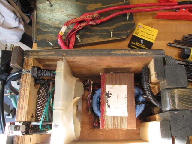
Gathered up parts to hog together and test before doing any assembly...
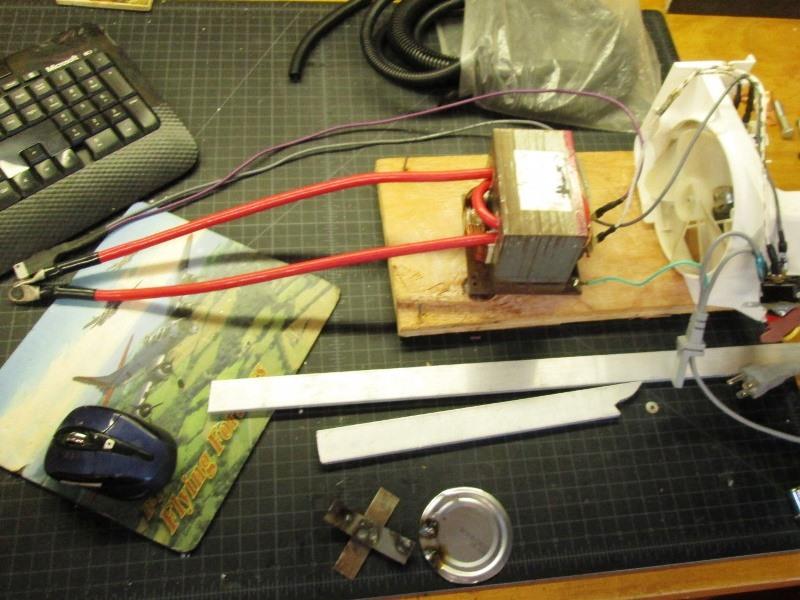
It works! Cobbled together and tested (not here on my bench). I wound #4 cable through transformer. Once plugged in, firmly press weld leads with some scrap tin and push the micro switch. BZZZT! Scary stuff 1st time. But it welds-never done this wasn't sure
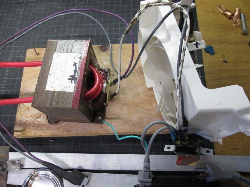
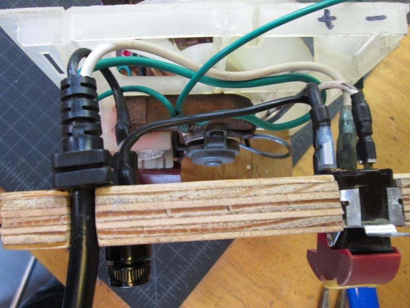
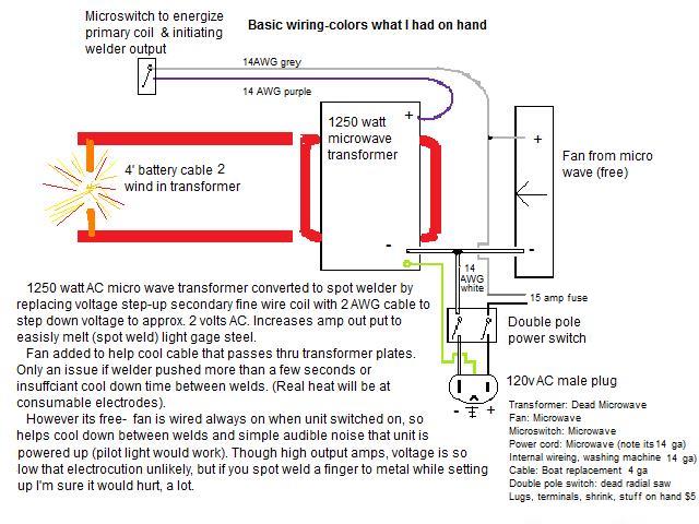
Just close up of wiring. Power come in goes to switch, from switch neg/return(white) goes to fan and transformer. Hot (gray) goes to fan and runs to momentary micro switch then to transformer (purple). Nothing other than fan is energized until micro switch depressed. Welding is a second or less. With proof of concept preceded with actual building.
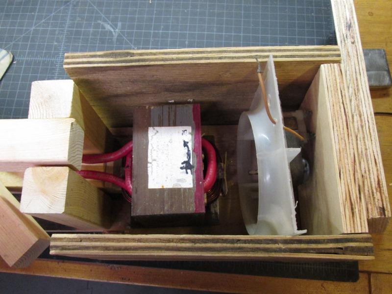
Went through several configurations but it was the size of fan that dictated box size. Did some need trimming of excess plastic on the fan, Still a bit wide. Just need to fill gap at arm supports.
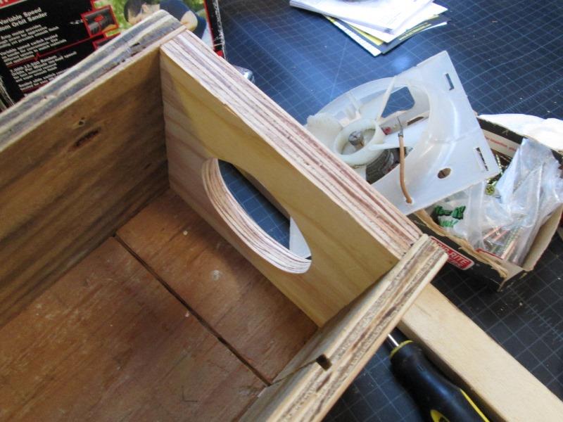
To mount fan cut slots in bottom, 1 side and top the fan will slide into. The other side has a flange remaining I can screw. Cut hole for intake
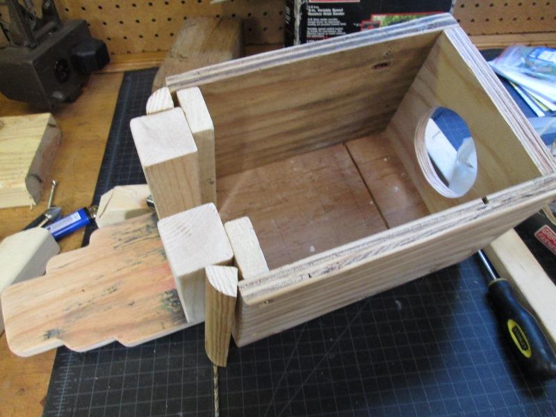
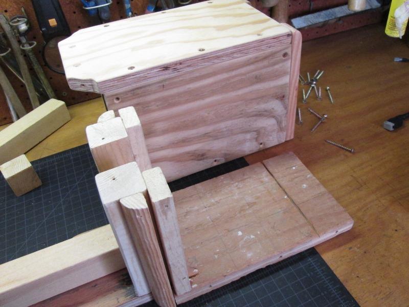
Basic box laid out. Upright 2x2s glued and screwed spaced for fixed lower and pivoting upper arm. Used 1x2 to bridge between to attach sides. Burned a 1/4" placing uprights so used the quarter round to cover 'oops' instead of re cutting plywood. Ran bottom long to support lower arm.
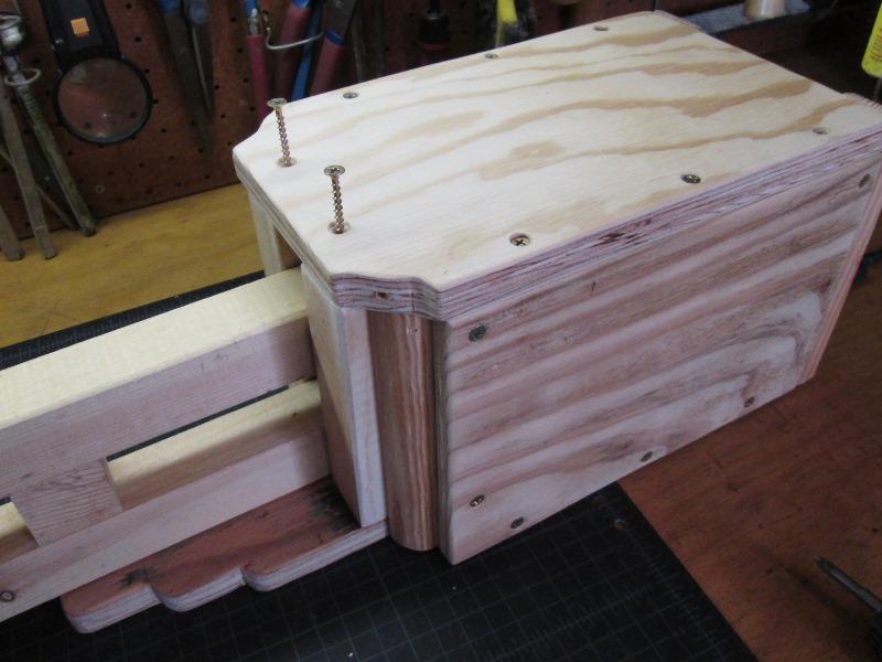
Cut top and screwed box together with arms loosely set.
Plan is once wired sides and top can be removed individually or as 'box'. Wiring will be to rear so will be fixed, front also as it contains arms. Little later I had to redo front- didn't allow for pivot arm bolt.
Started arm construction to hold tips. I played with this for couple of hours trying to get best mounting. Occurred to me though, and one persons video who used plastic which melted welding that as hot as this may get wood may not be ideal. Plus the 2x2s are large for getting into tight places. Originally I was going to use some 1/4x1 aluminum bar I had but couldn't see easy way to mount tips.
Scrounging thru junk came across some 1/2"x1 1/4 al bar (old door push bar). Whoo who!. Wide enough to drill and mount lugs, will dissipate heat and small getting inside stuff.
Perfect, drilled to accept 1/4 bolt
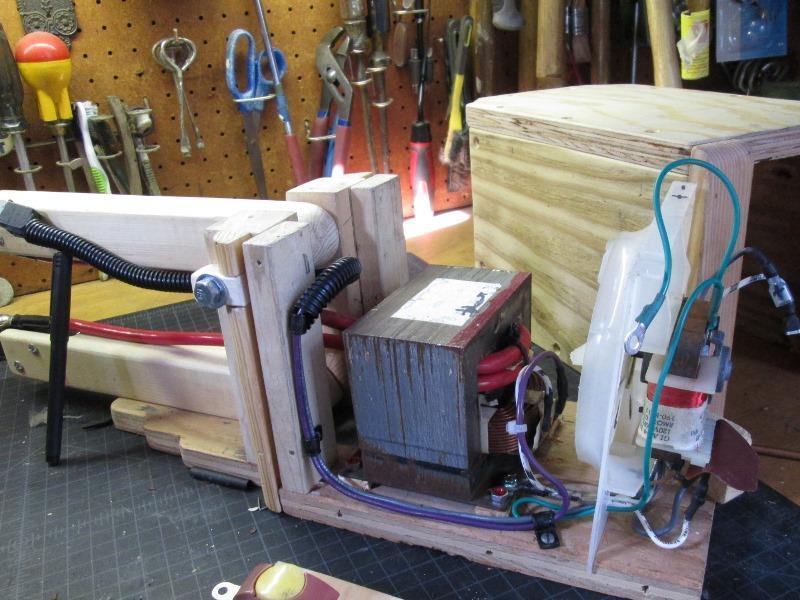
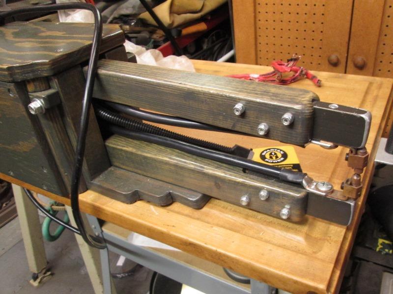
Cut 2 at 4 1/2" long. Laying out length at cable to locate transformer
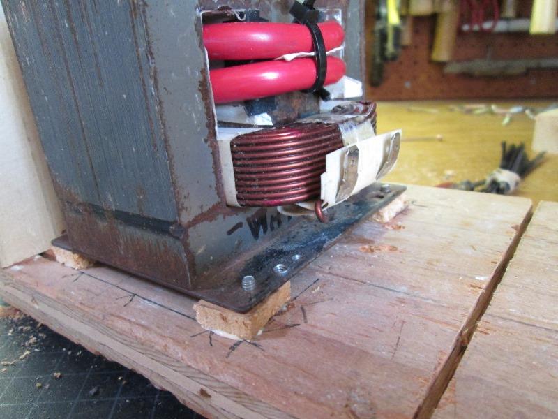
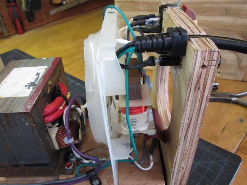
Mounted transformer using standoffs for air flow.
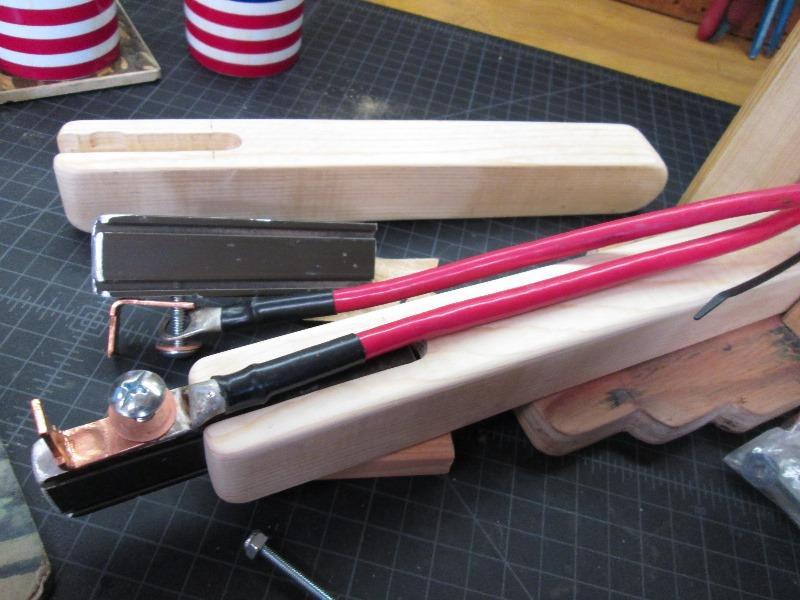
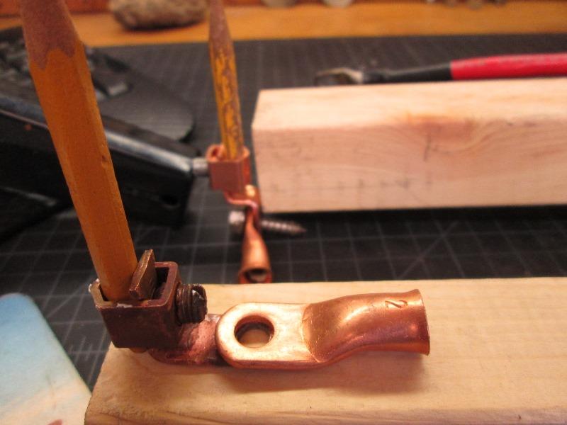
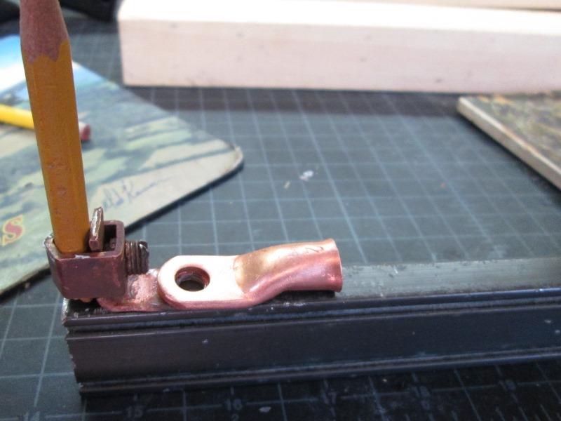
routed groove for tip mounts
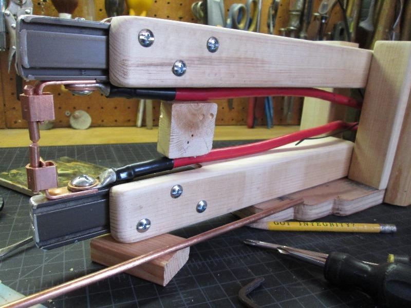
Set up tips to ensure placement, screwed bottom arm to base. Drilled thru arms mounting with 10-32 screws and nylocks.
And oversight became clear getting ready to mount upper arm...when I realized no allowance for pivot bolt.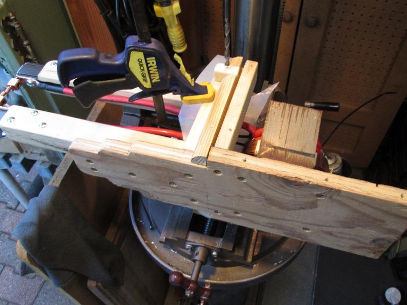
Mostly due to the quarter round I used instead of re cutting plywood when I made initial error. Instead of fixing I made another-- that I now get to fix. As this is all glue and screwed I used ocillating saw to cut out chunk of the 1/4 round both sides. Glued in a small square blocks for pivot bolt. Drilling this with everything attached was necessary to ensure match drilled, but painful. Used 12" long 1/4" bit then back from both sides with 5/16".
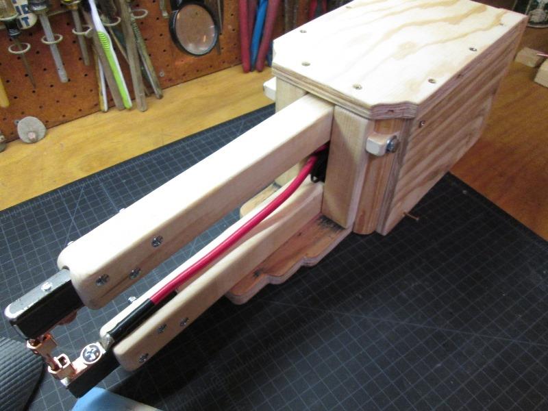
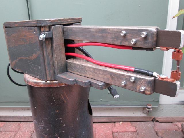
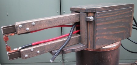
Cabinet/arms done. Now to wire
Chassis wired. Ready for rear switch back
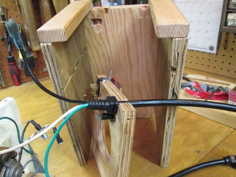
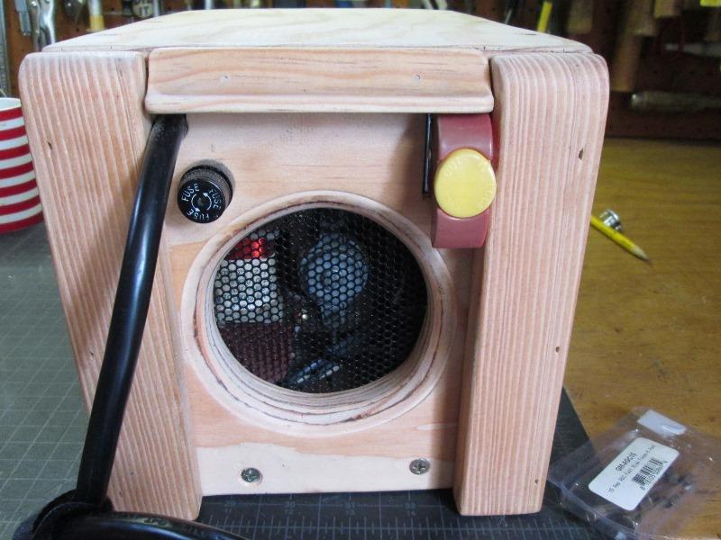
To the top of rear cut notches for cord and switch. Note I changed to this 14ga black cord I had verse the gray one out of microwave, easier to restrain. Drilled for fuse holder. First though I routed the fan intake hole with round over bit. Top lightly clamps cord, its retaining block fits notch in top. Not added here yet but cut another slot in top that switch mount tab goes into.
Wired. Added an extra earth ground for possible receptacle addition without rewiring, easy to tap power/return from switch.
Wiring fairly secure.
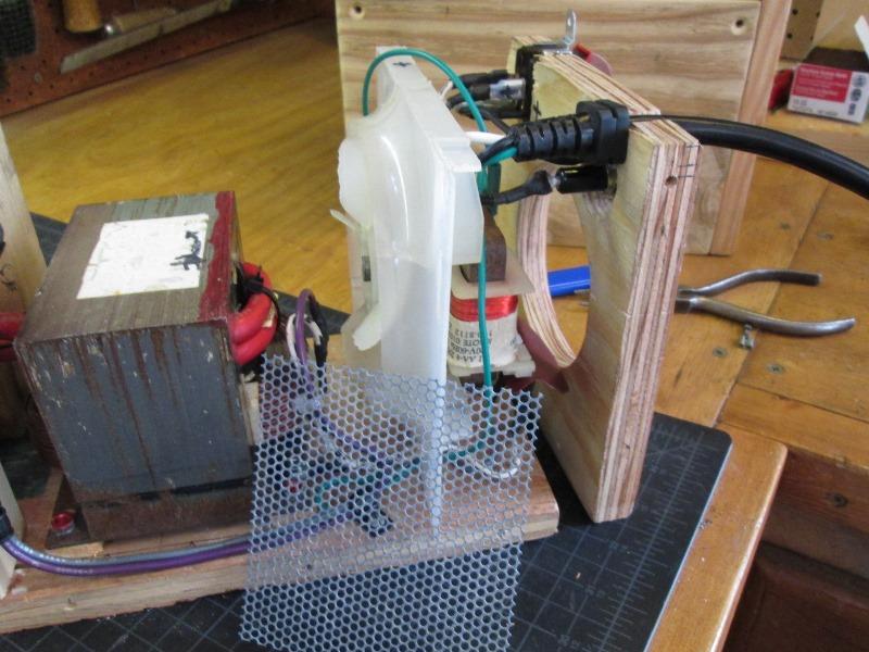
Adding screen from old CPU to fan intake hole.
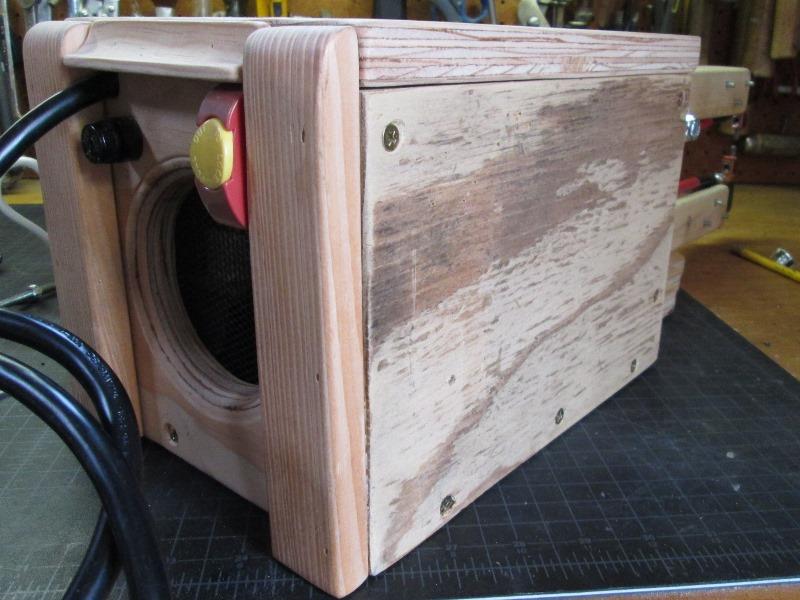
Tried to sand out the plywood, pretty bad. Add the side 1x2s to recess switch and fuse holder, they were kinda hanging out there. Added the top piece of scrap trim between to keep debris off top of switch.
Kinda wishing I hadn't used the old ply wood. This and front arms looks fairly nice. Box itself looks like Id been parking my truck on it.
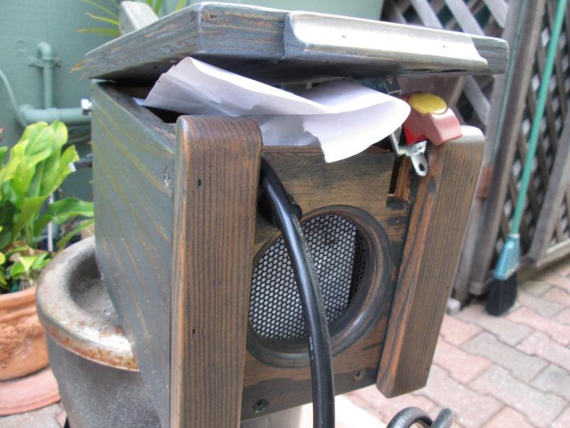
Answer; some old charcola stain.
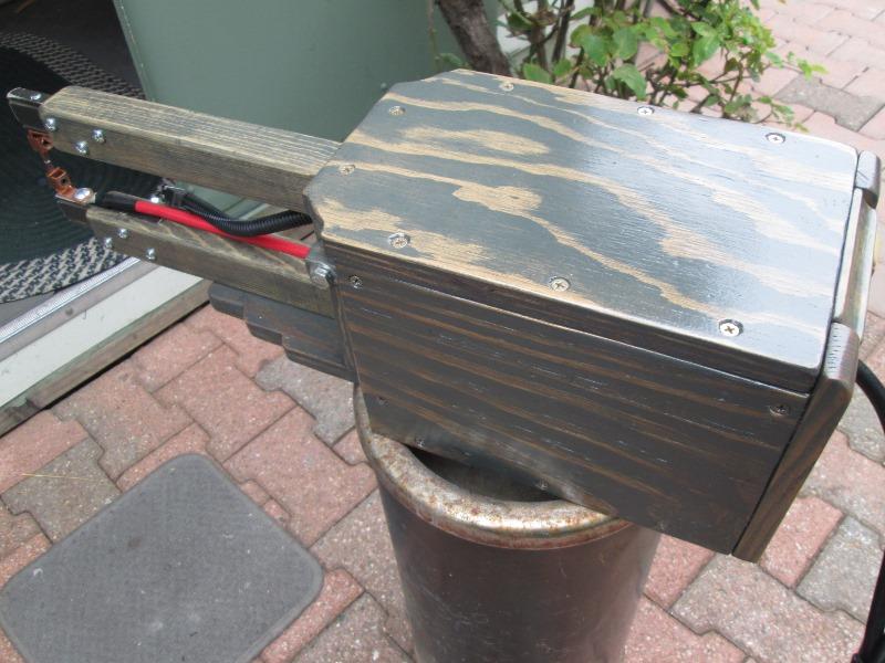
And a few coats of varnish...:)
All in all this DIY spot welder is pretty amazing. Does have some draw backs. One is the duty cycle. Generally not a problem but like I finally managed to do, is melt the cables due to letting it over heat by continuously using. Start of this page shows retro fitting larger ga cable so should help-mostly though just not be in a hurry.
Many add handles to their units but I just don't lug around. Second is adding spring to lift top arm. Which I was going to add. However in use its seems to be easier setting up putting material in between points with arm weight holding so haven't pursued.
On the to do is 1. Adding a thermo button to disconnect trigger would be nice but entails measuring to see what normal operation temp or just at max rating of cable of 275°. Even paying attention, if trigger switch stuck runaway welder will self destruct. So more of a fail safe.
2. Adding a relay and small transformer to trigger switch line with 12v so trigger (micro switch) switch only sees load of relay and not AC voltage/amps. Hasn't been an issue but holding that little live AC switch is the only thing that literally puts fear into me.Back to shop repurposing section
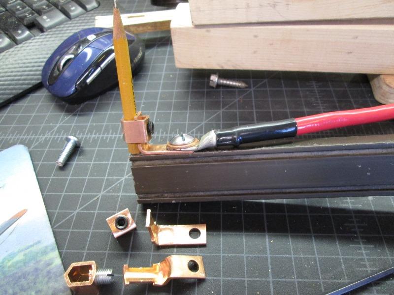
Replacing cable on my DIY built spot welder, decided to document it and include original project (below)
Few years ago gutted old microwave to use cabinet in shop. Bit later used the internals, primarily the transformer to build a spot welder. The DIY spot welder works awesome- but you have to let it cool down after a few welds. (IE cable is rate considerably less than amps this can generate, and if not given chance to cool will overheat.
Recently made a 22ga metal box for impact sockets and managed to melt the #4 battery leads of my spot welder. Had 30+ welds and towards the end I just pushed it to far. I knew it was getting hot but just one more weld- POOF thick smoke was pouring it of it. Dumb ass...
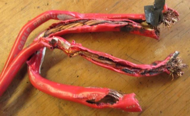
It didn't short but the insulation (actually don't know that it can as cable wound around isn't physically connected to electricity) simply melted, fused together. Took a bit of effort to remove from transformer.
Waiting for new heavier #2 cable on order decided to document my original build. I hadn't originally because there are literally hundreds of DIY builds and youtube videos.
My original build was mostly stuff on hand, specifically the #4 battery cable. While it worked, the new larger #2 cable will handle/pass more current before heating to point of melting. I've already repaired and welder does perform substantially better with the #2 cable. Comes up to welding heat a lot faster and seems to be applying more power.
I noted when removing old cable where isolating paper plastic didn't stick. So I wrapped new cable with some paper masking tape where its wound around. Not sure a good idea but in case I do this again will be easier to remove cable.
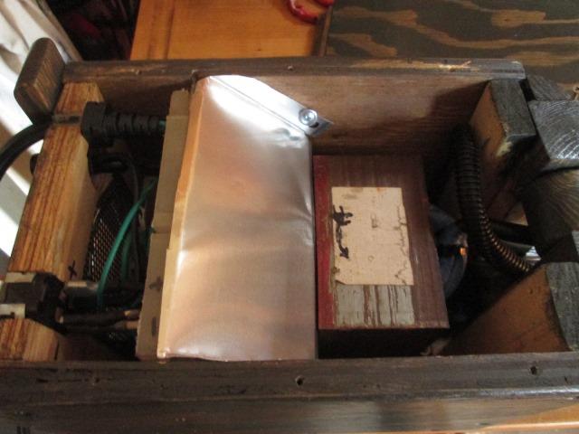
Also added a diverter out aluminum flashing to force more of the fans air thru transformer and windings. I'll note here on mine I wired the fan direct to main power switch so that it runs continuously when unit turned on.
Why build a spot welder? Other than kinda fun, practically seldom need so cant justify cost of factory made. It does come in handy. IE I recently duplicated box for impact socket set.
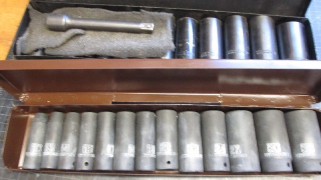
While I used mig to finish & plug weld piano hinge, wrapping corners make box simple project spot welding it.
Anyway new and improved. With the new cable I have $20 into it.
Original DIY sheet metal spot welder project
3 1/2 years ago had need of a spot welder. After pricing new ones came across folks building form old microwave parts. Watched many youtube videos gathering info, it actually is pretty simple. Basically use transformer out of MW. Remove the secondary winding and replace with minimum of 4gauge cable wrapped 1-2 times. This changes the output from high 120V line voltage/low current to low 1.5/2.5V voltage/high current. Its the current, not voltage, that welds. Add a power switch to power transformer (& fan). On lead to transformer splice a momentary switch (micro switch from MW). Add weld tips to ends of secondary cable.With both welds tips firmly against items to be welded creates a loop. The highest point of resistance is at the weld tips and the metal between which creates the heat resulting in heating the metal and the force applied is what fuses the molten metal together. Simplified but that's really it. With power turned on depressing the micro switch energizes transformer. The process only takes a couple of seconds. Note some heat is generated in the main cables, which inst a problem. However successive welds and the cables get hotter and hotter as they retain heat, so adequate time between a few welds is required. How much depends on your setup. Point is, limited duty cycle-adequate time between welds IS REQUIRED.
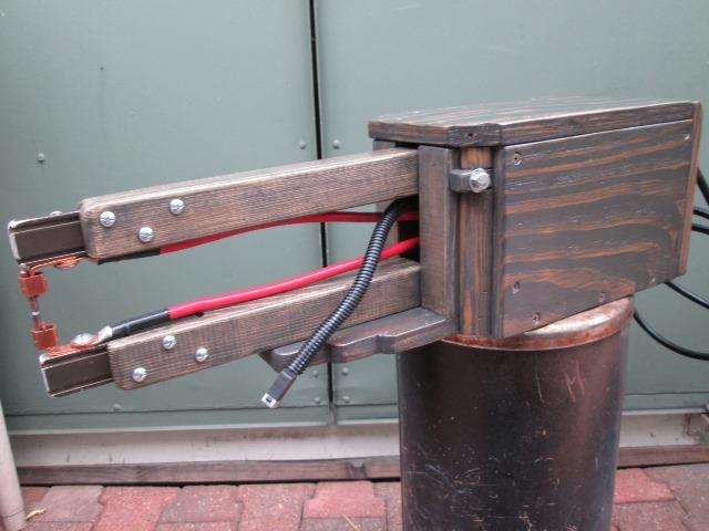
Basic designs of mechanical arms that hold tips, wiring etc is similar. So entirely dependant on tools, parts, skill set and how much time spent. Most have platform to mount components, stationary arm for fixed weld tip and another rotating arm to apply force and other weld tip to items being welded. That about as much detail I'll offer. Too many good videos outlining, other than the most popular video IMO isn't the best build so watch as many as you can find.
My only recommendations; #2 ga wire (battery cable), use fan wired directly to power switch so its on whether welding or not.
Output Amps generated are very high but output voltage is 1-3v, mine measures 2.5 volts.
| Parts is Parts... | ||
|---|---|---|
| MicroWave: salvage | Parts on hand: | Purchased: |
| • 1250 watt transformer | • 4' 4ga battery (updated 2ga) | • (2) copper lugs; to hold 5/16" tips |
| • Microswitch | • 2'sq 3/4" plywood base/box | • (2) 1/4x1 1/2" screws; bolt cable to lugs/arms |
| • Power cord | • 4'x2"x2" arms | • 5/16"x 6 1/2" bolt, nut,washers; arm pivot |
| • Mics wire | • 9x1/2x1 1/4" aluminum bar; tip holder | • 5/16" 12" copper round bar; to make tips |
| • Fan | • Fuse & holder | • |
| • - | • Power switch | • Insert DATA for row 8, column 3 |
| • - | • Mics wood scraps; 1x2", 3/4" round, | • - |
Obviously parts will depend what you have on hand, can salvage-what you want to build. Note switch can be single pole on hot/line side.
Back to Our shops home page