Modify AC/DC power supply
 Always seem to be playing with electronics or laying out circuits to perform some function, testing some item that doesn't work or want to modify. I have an old AC/DC fixed voltage power supply. Works but not every thing is 12volt.
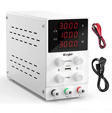
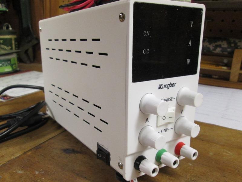
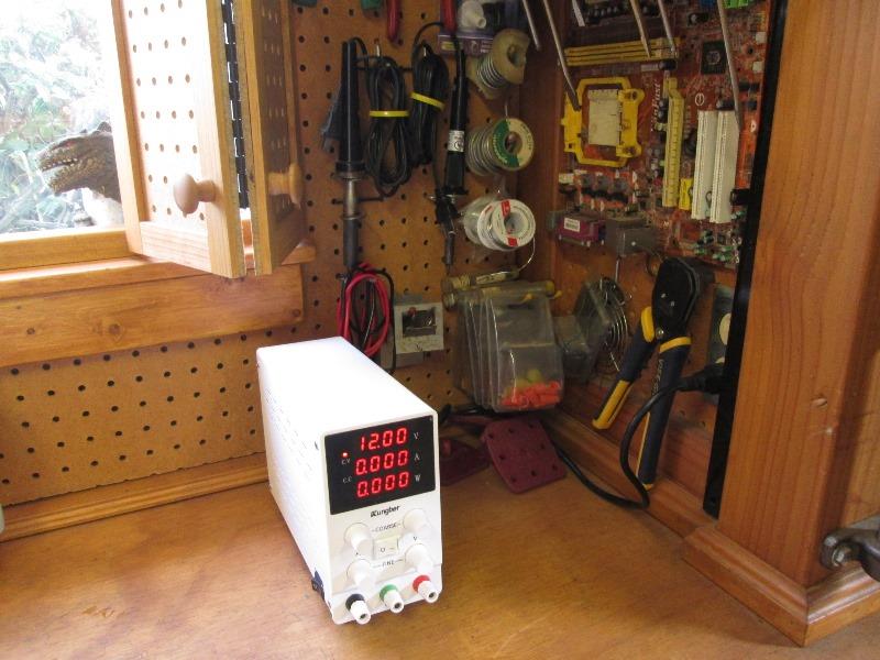
At any rate received for Christmas an inexpensive power supply that's been on the wish list forever. Variable 0-30 volts, 0-10 amps with a watt meter. 4 digit readouts- load output can be limited either volts or amps. Well for me and my needs wants its awesome.
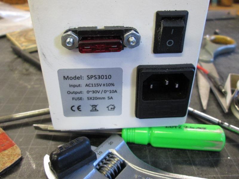
Kungber SPS3010: https://www.amazon.com/dp/B08DJ1LP2Y
If your a professional or work on sensitive high end equipment this isn't the unit, this is an inexpensive that will work for most 'home' shop use.
There are literally tons of these power supplies available, different feature, configurations, price etc. This one of the least expensive had good reviews, 4 digit volt, amp and watt meters, coarse/fine adjustment for 0-30volts & up to 10 amp output.
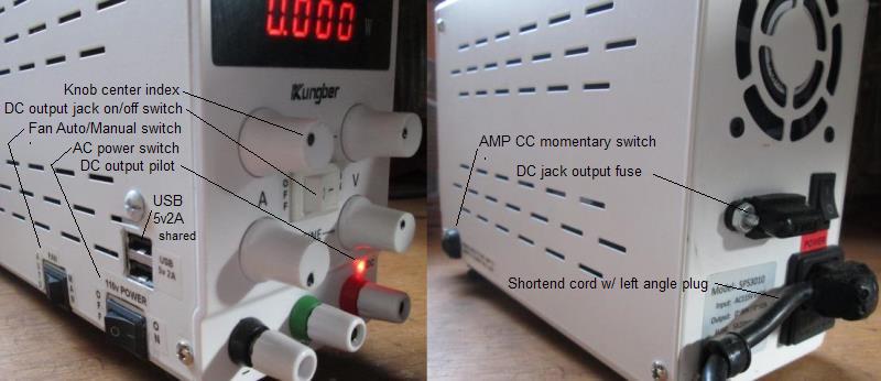
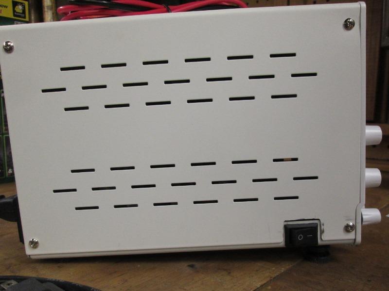
It doesn't have a disconnect switch for the output and its main power switch is on back of case.
Which is point of this page, adding power switch on front of case. Don't know that output switch needed but would be nice.


So taking my warranty into my own hands...It appeared on customer review pictures there would be room for power switch on front. However setting on the work bench slightest pressure the case would slide on workbench top. Units weighs less than 3# and its feet are hard plastic. I have some soft rubber feet from something else, they also have step so could be installed so the case angled higher in front. AS they are larger diameter it means removing old feet, enlarge hole in bottom of case to insert new feet. That's when I decided to completely disassemble power supply.
- Replace rubber feet, angle case
- Add main power switch to front, add external DC output fuse
- Remove new power switch & moved to side, add DC binding post disconnect switch in its place
- Add USB ports
- Add switch to turn on fan manually or auto temperature control
- Add Constant Current (amp) momentary setup switch
- Shorten power cord
What we ended up with as outlined below...
Here are the new feet installed after the fact...
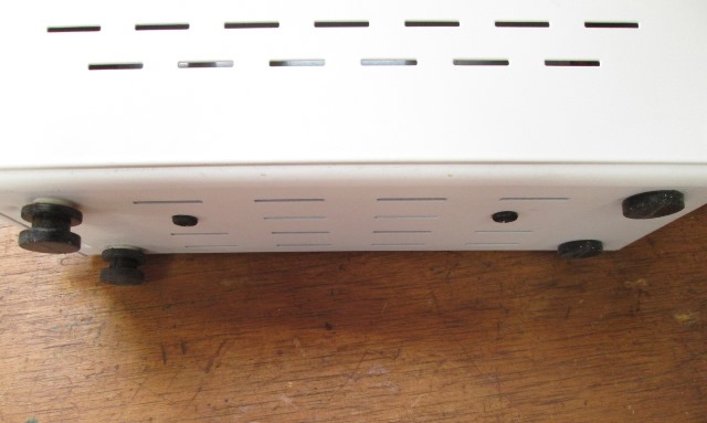
Note; when drilling I started from inside of bottom plate drilling out. The metal is very soft and smushed outward about 1/8" which makes the feet stand further out, good thing on the front so the rear holes I drilled from out side in so feet are against bottom. This raised front of case about 9/16" higher than rear, easier to see face, more clearance using the binding posts.
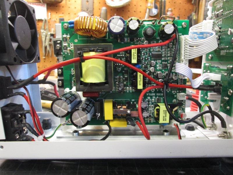
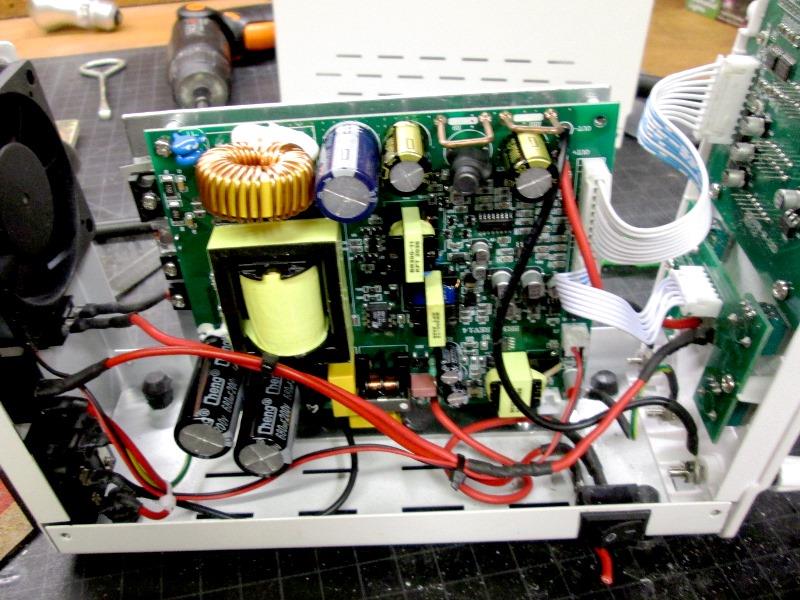
To drill for feet as mentioned I removed power supply internal components to ensure no metal debris. It also would be easier to add the switch in front.
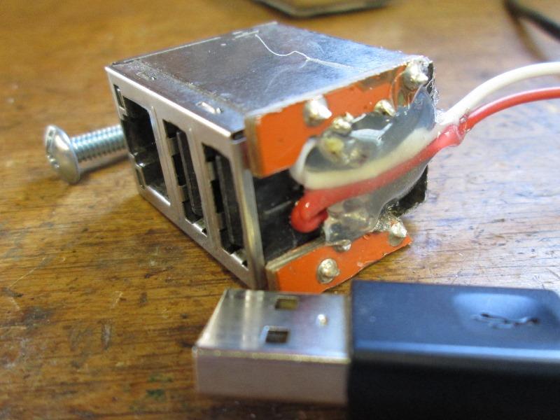
Well there isn't room. What I ended up doing was remove the USB power port, more important to me to have easy on/off.
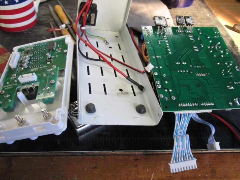
And disassembled, removed main board from heat sink to access solder pads. Filed out the hole where USB was and installed new switch. Disconnect wire from factory switch to board and extend it to reach new switch. Wire from new switch goes back to board.
I will mention all the plugs, ribbon cables, fan etc, the halves of the plastic plugs are siliconed to their respective ports. I guess for vibration?, just took a bit to clean off to be able to disconnect. Down the road when Im sure Im not going back in likely reglue. Also wires from switch and power receptacle are soldered. Aren't removable without de soldering the wires. I de-soldered from board as they needed to be rerouted anyway. None of the factory crimped on connectors capture wire sheath, they are crimped & soldered but wire strands are exposed, any flexing will break wire strands. I slipped on heat shrink to all of them to keep flexing
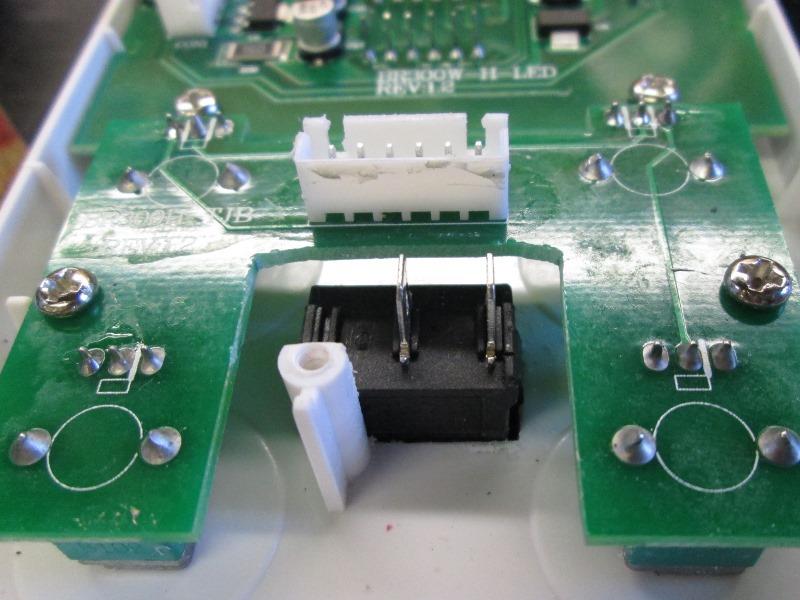
Just close up of new switch mounted. Had to file the original post the USB mounted to for clearance. Factory rear switch now feeds new switch.
 Decided to add an external DC output fuse. Disconnected the output wire from board to positive binding post, ran to fuse, from fuse back to post. The unit has internal short protection but this should help board from seeing one of my pastimes-creating a dead short..
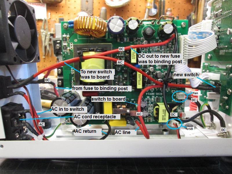
New power switch and output fuse Wired- not too messy. ( I ended up moving the new switch to side of case)
Just wire routing up to this point. Tested everything works well-however I had plugged fan into USB port so it was running, duh.
- DC output binding post switch
Main power switch moved to side. Not optimum but power switch on the side still easier than rear. Mounted on the bottom flange so cover can be removed. The DC output switch doesn't stop output, only disconnects the positive binding pos (meter still shows voltage but post immediately off).
TBD I may reinstall the USB IF I can unsolder case from its board. Insert thru metal cover and resolder board. IF I can unsolder and install usb I may add a 3way switch from the usb port and add a small 0.15 amp HD fan. Switch USB or constant fan if running high loads. That's a big maybe. I don't really need another USB charger but If I can why not. The fan addition I will do. Whether on 3 way switch or just on/off if usb install fails.
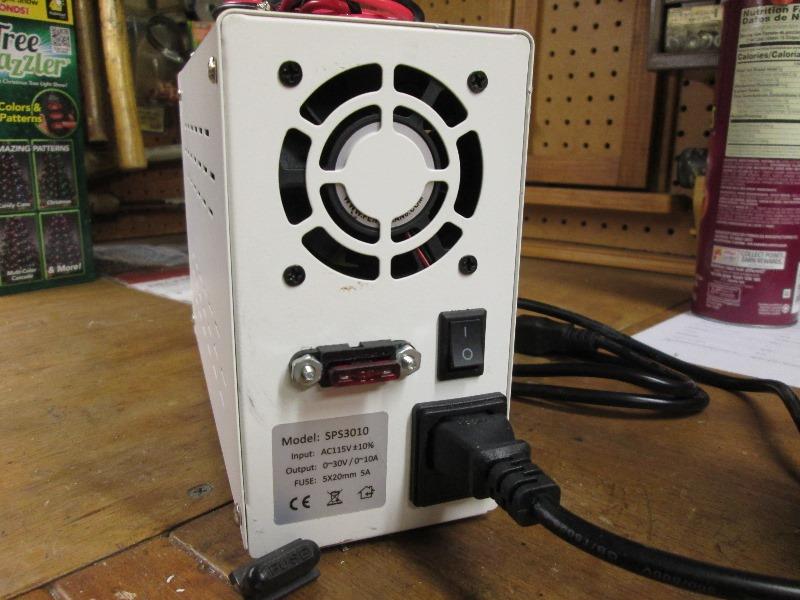
And DC output fuse.On the to do list is purchase a left angle AC cord as the factory plug sticks out the back about 3" pushing unit out away from wall.
Nice!
- Reinstall USB ports.
Laid out where it will fit and cut hole to expose 2 USB ports.
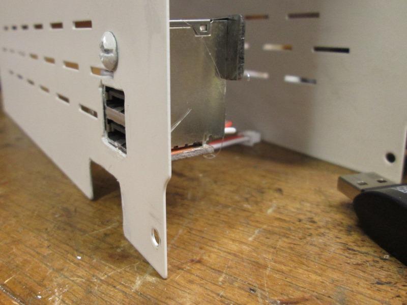 Mounted to case with screw going thru cover and can securing. Small piece of flat bar on the back with nut so as not to crush can. Originally was going to mount to a piece of angle bolted to bottom of case, but this was just too much easier. I'll just need to make sure when removing cover USB can doesn't snag wires and with cover partially removed unplug from USB port.
Works. I used a dremel to bore small dimple then filled with paint to mark mid of all knobs rotation.
- Fan control
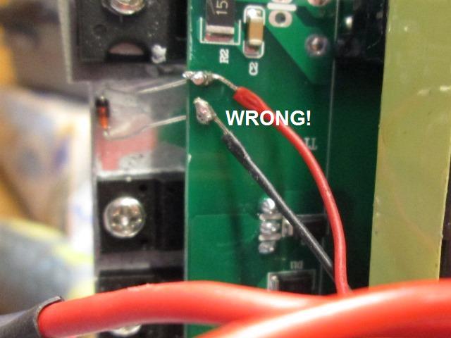
How I incorrectly wired then fixed... Looking at the factory fan discovered fan is controlled by a small temperature link, jumping the 2 terminals its soldered to would turn on fan. Simple BUT WRONG!!! DON'T
Worked but once wired switch jumps the 2 terminals fan comes on - flick off, fan goes off but comes on when detects set heat temperature. HOWEVER connect a load and turn on fan it disconnects the DC output? FAIL. I hadn't checked meter when testing for this but I dont understand what it does. When high temperature is detected it completes circuit and allows fan to come on, DC output unaffected. Manually jumping the terminals operates the fan but kills DC output. Puzzling.
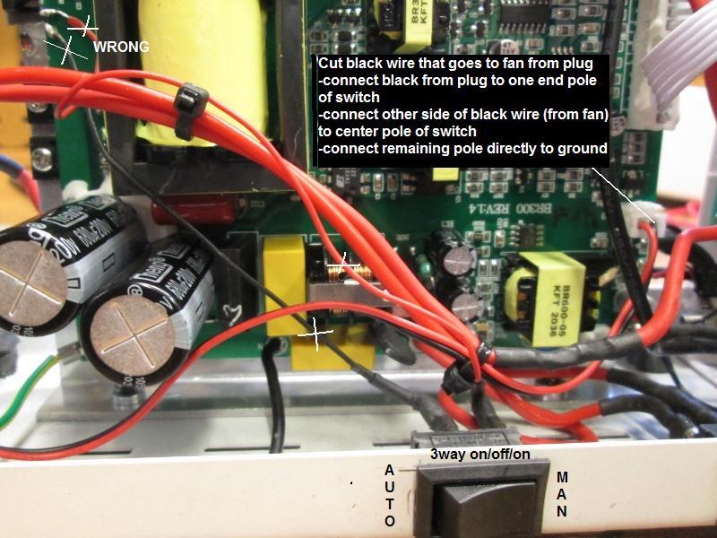
Further probing, found the red pin fan is plugged into is always 12v hot. So the temperature probe connects the ground pin of fan plug to ground but not directly. Grounding the ground pin at fan receptacle manually turns on fan without affecting DC output. So the little temperature link triggers something to ground the fan plug.
No picture so doctored fail, removed added wires from switch to board. Cut ground wire from fan, connect to center pole of switch. Connect black wire from board plug to one terminal of switch. The other end terminal of switch directly to a ground. Now it works. Ground from board plug- thru switch to fan for auto as designed, or fan ground thru switch for manual on. Had I known the fan positive lead is always 12v hot, could have used that to add smaller fan- oh well this works-Im done.
- Current control- AMP limit setting
Next is setting the amp limiter (current control). Procedure is to connect a lead between positive and negative binding posts. Dial in the maximum amps you want to see. Disconnect jumper and connect your load. The current control is nice- your load will never see more amps than you've set but the voltage can climb. But its the steps to set when a simple momentary switch would have the same outcome- grounding positive to negative post to set current. So that's what I did.
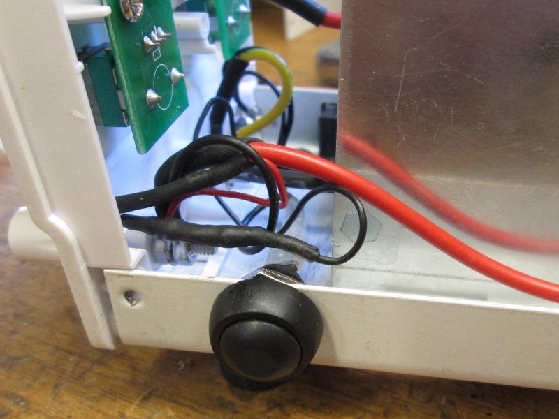 Push/hold the momentary switch before connecting load, set up current control if you want/need to max amps without playing with a jumper wire. No clue why this isn't done. Except that- if load were connected and you jump neg/pos bad things could happen. Its my power supply...I mounted to opposite side of case other switches.
And labeled.
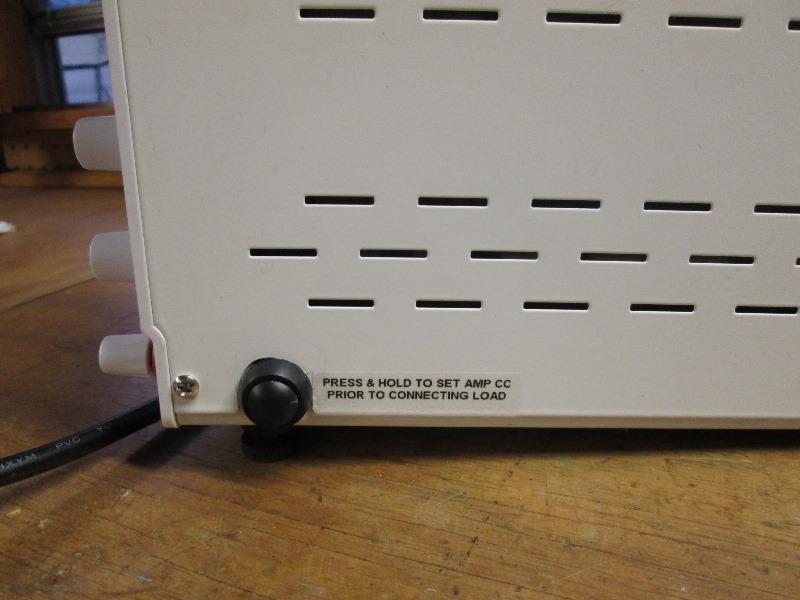
New CC setup momentary switch
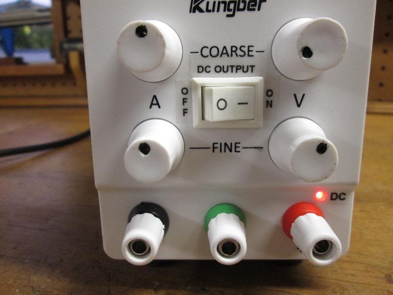
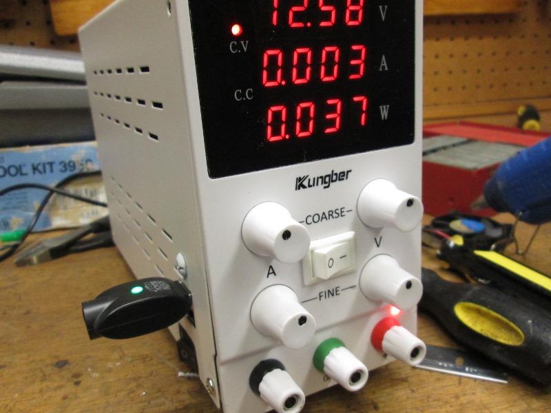
Front DC output switch and pilot
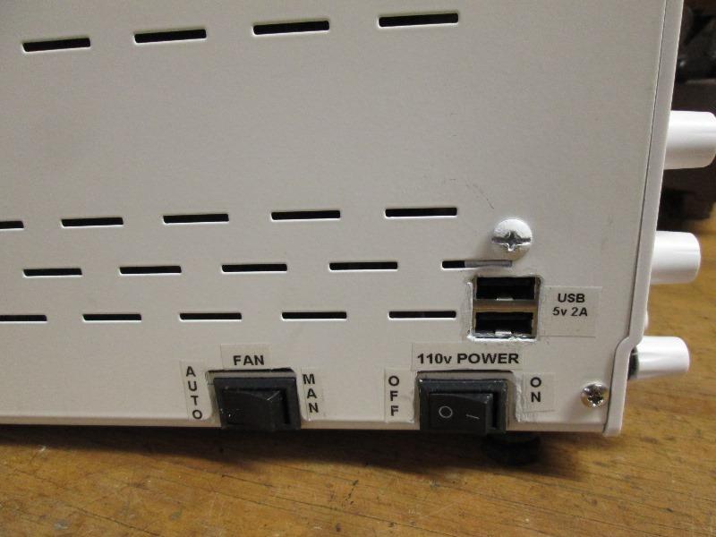
And main power, fan and USB, looks a bit hacked because it is. But it works.
Last is power cord. Way too long , sticks straight out the back
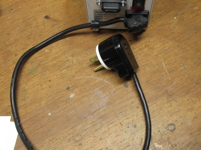
Plan was to replace cord with a shorter left angle C13 female plug (computer) and a 90° male wall end However I couldn't find one with ends and as short as I wanted. So cut/shorten the power cord to about 18" using a right angle wall plug so cord will hang down from wall receptacle. At the computer (C13) side I cut and remolded to make it a left angle, only sticks out about an inch.
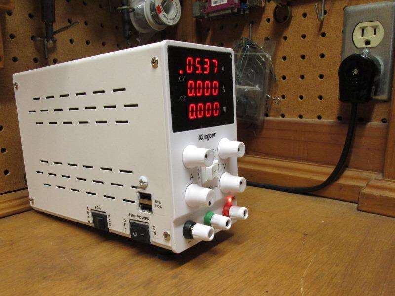
Allows pushing the power supply almost 2" closer to back wall. Simple fun project, modified for intended use
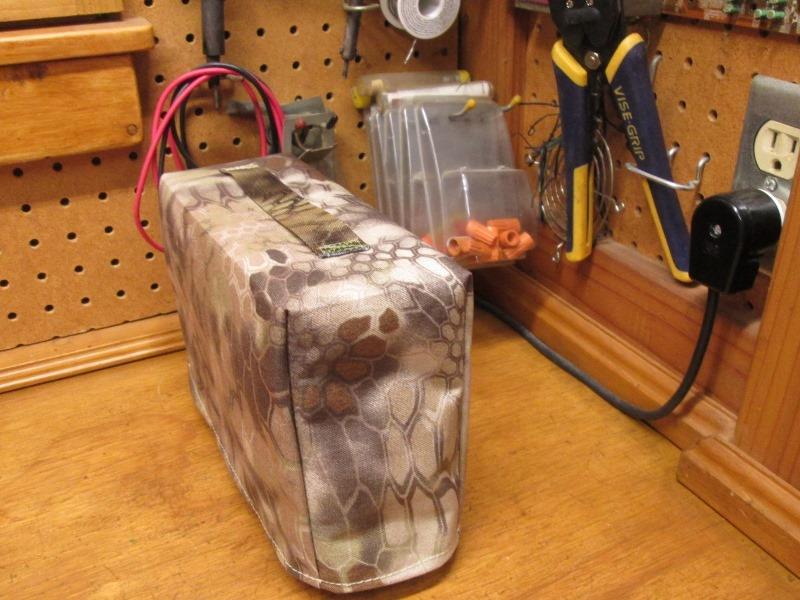
Quite a bit later... made cover to keep clean
Back to work...
Back to Our shops tool mods section