Using PANCAKE compressor for workbench air
 Intro-The what & why
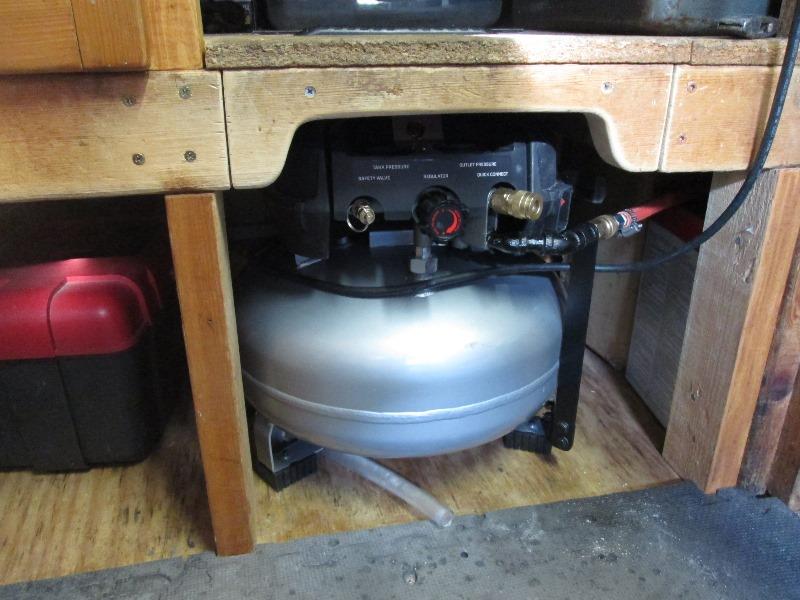
• Modify workbench to store & use compressor in shop
• Modify compressor, add quick coupler to bench
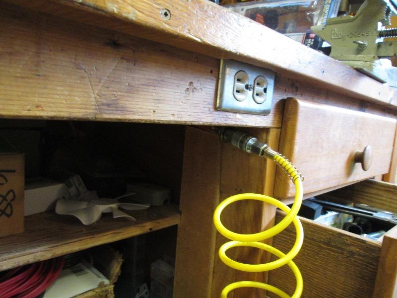
• Electrical Add dedicated switched receptacle
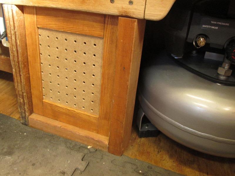
• Box bottom of added workbench leg-
• Door for space between old & new leg
• Relocate drain valve
• Add low PSI switch, 3-way switch to select 125 or 175 PSI
Update 5/2021
• Add gauge 'window' to shelf, opening the lid to see got old
• Add 3rd Q/C and air line hose reel, resurface lid
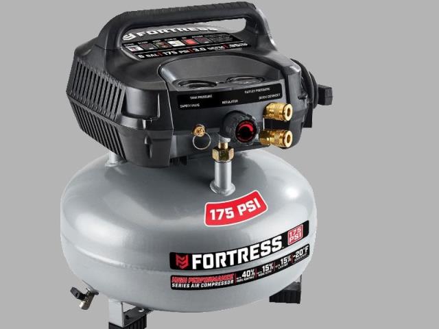
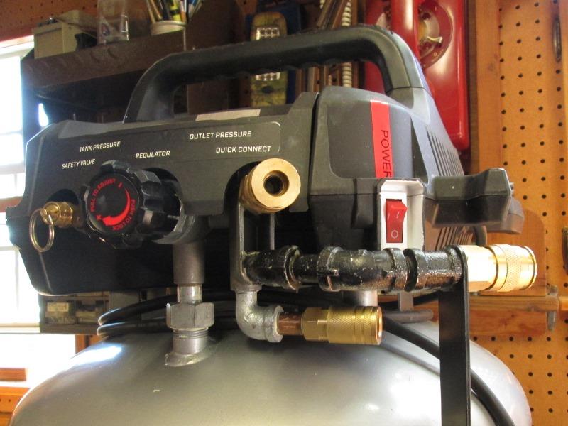
Recently had need for a portable air compressor to run nail guns etc to reside a house. Picked up this 3 gallon pancake compressor from Harbor Freight for $120 dollars
For the task it worked well and paid for itself. But part of the justification was use around the house/shop where I usually have to run 100' hose to reach stuff. This would work well for those needs. Once I brought it home, put it in the storage shed but soon realized not very convenient- easier to just run hoses. If stored in the shop be handier, if I could find place to store it. Its about 3" to tall to set under workbench.
Somewhere in this process I realized if stored inside the shop I could use for air at workbench instead of running hose from main air compressor.
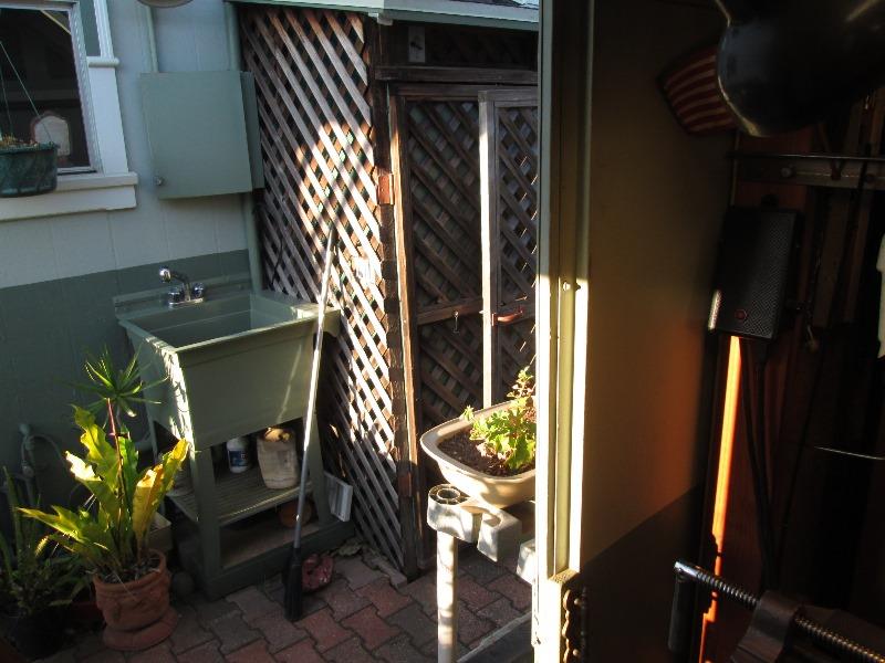
It lives in a lean to just outside shop next to sink, most air needs (cutting/grinding cleaning) are done outside and has worked well. For those occasional needs to run inside shop kind of a pain. Hose draped across deck and inside shop either tripping- getting tangled in cords-just doesn't work. Having air inside for light use would be awesome. So revisited at what it would take to store in shop.
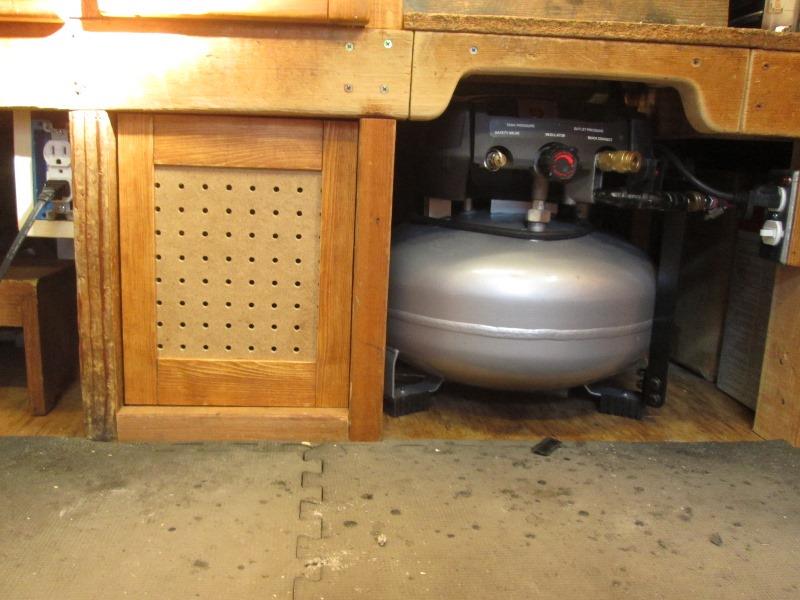
Where to put Modify workbench
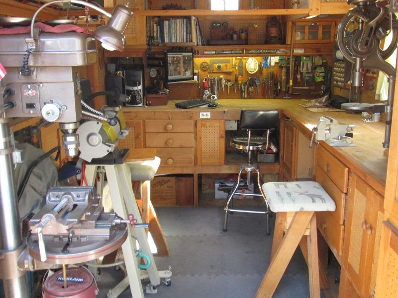
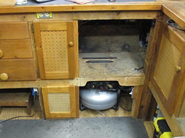
There are only 2 options, on floor under shelf either at front bench or at the side under the vise.
Though I seriously considered removing the compressors handle so it would slide under shelf anywhere, that would defeat its portability. I also considered making a handle that didn't stand as tall, then notch the shelf support 2x4 so compressor would fit. That left as only option under the front shelf as the 3 drawers under vise have a lot of weight and the support cant be cut.
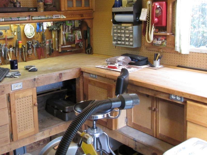
The shelf at front could be cut, its only used as foot rest when setting at bench. Would need to add leg to support end of shelf support. Without hesitation started cutting...
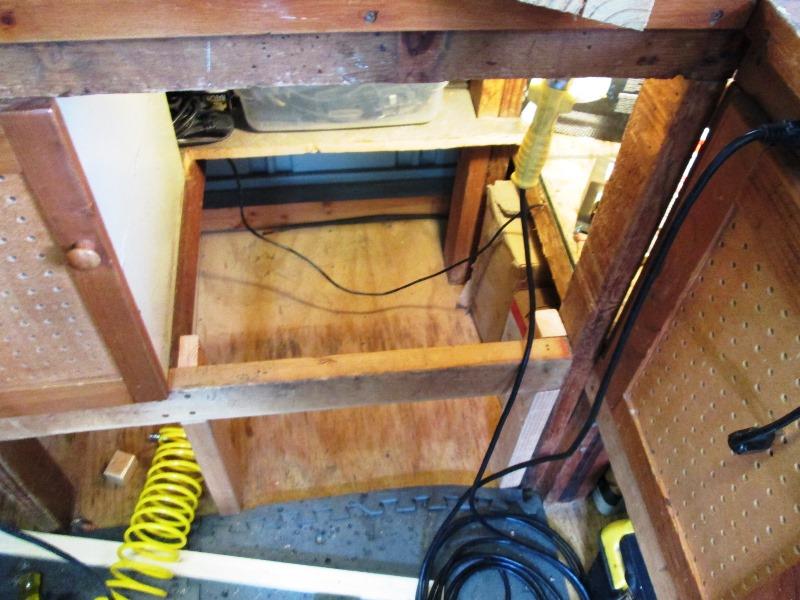
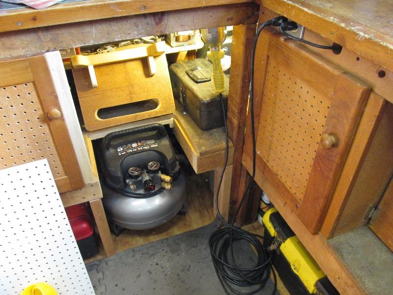
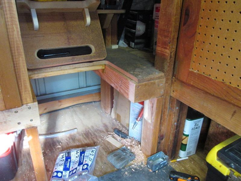
Cut and removed the end of open shelf board. Add 2x4 leg at what will be end of shelf, another at corner leg. Plan is to box in around compressor, cutout front 2x4 and replace some of the shelf. Only needs about 10" of open area for compressor to slide back.
Sat the compressor to where it will live and started boxing in shelf support before cutting front support.

And compressor trapped. Plan was to lay shelf on new structure, trace, cut and attach. However cant remove compressor, cant lay shelf down to trace because handle sticks up and I don't want to cut the front support until the shelf is reattached to tie all the structure together...
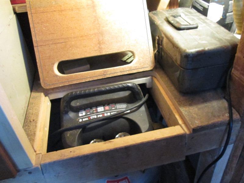
I ended up cutting slot in shelf to clear handle so it could sit flush. Tracing out realized if I cut opening 1/2" larger all around piece could set back in, regain foot rest and shelf. Removable to store compressor. Cool, reattached shelf and cut the front support. Added 2x2 on left for small door to close against.
What I should have done was notch and run added leg full height to bench top.
Decided to attach cut front support piece to shelf piece as its only particle board.
Cut front support to lighten and open access to compressor. When putting back decided to hinge.
Add gussets to front support. This works slick-on the fly changes usually bite me in the end but only round to it is bracing the short added leg. Strong but if hit at floor could leverage and cause it to move. I'm probably going to add a shelf to brace.
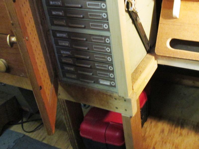
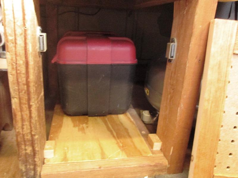
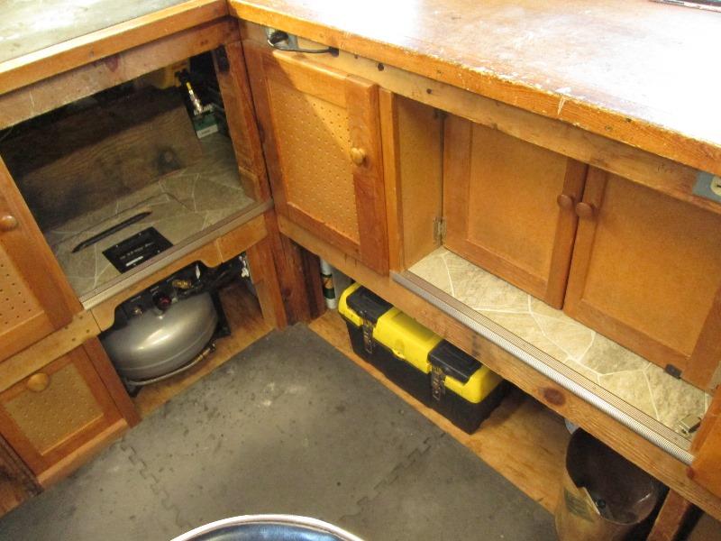
Adding shelf under drawer cabinet would tie the legs so cant move, also be easier to access the air tool box. Make matching door.
But have compressor storage, access to air inside, retained foot rest and shelf. Fun practical project-I like it.
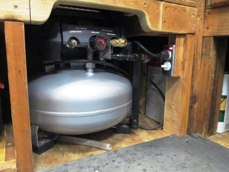
Modifying the compressor Add bench Q/C
The hose sticking out front gets hit plus hose comes to where I'm using it from the left so kind of in the way, either draped in front of or behind where I'm standing.
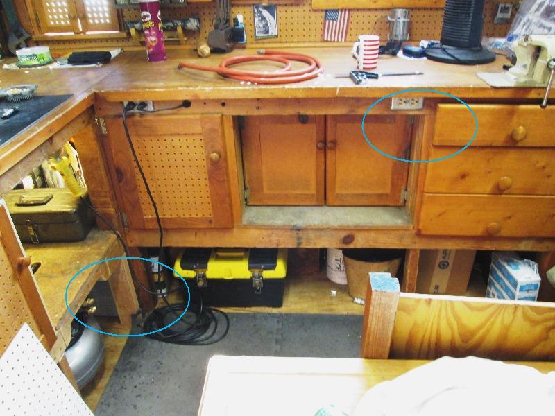
Adding a Q/C under front of bench, run short hose to plug into compressor.
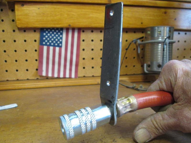
Used piece of flat bar made mount for Q/C. Route 8' hose behind bench over to air compressor.
A LOT more...wow!
Having access at bench has been on the wish list for ever. Always wanted to hard pipe from main compressor into shop, Other than expense, physically routing from house to shop, around thru cabinets would have been a nightmare.
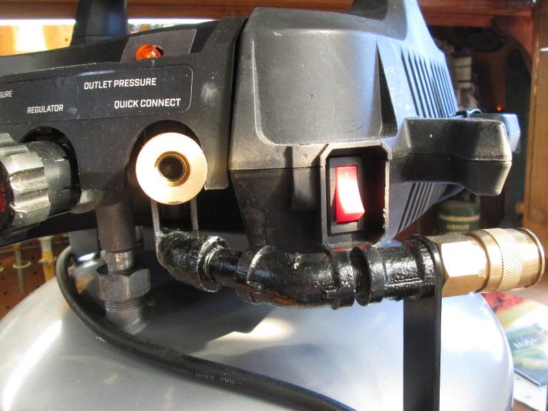
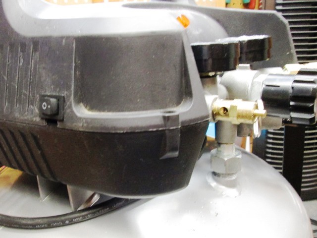
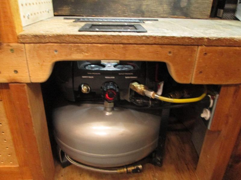
For the routed hose that plugs into compressor, relocated lower outlet. Used a few fittings to point to side. Also added pilot light denoting compressor switch in on (auto) position.
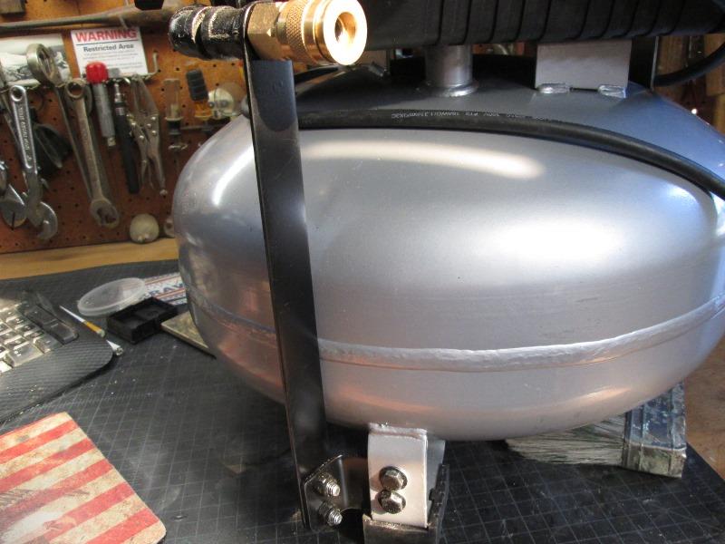 Added support so outlet doesn't unscrew itself or exert leveraged force to pump outlet. Couple pieces of bolted flat bar.
And done...On the round to it is drop a receptacle to lower bench leg, probably with switch so compressor can stay plugged in.
Electrical and bench leg...
Sooner than later, cord draped out front, having to locate and plug cord in moved this up. Adding dedicated receptacle with a switch so compressor can stay plugged in. Addressing the added leg, even though secure at top, hit at floor just a lot of leverage and it moves. The new leg is very structural in supporting the shelf
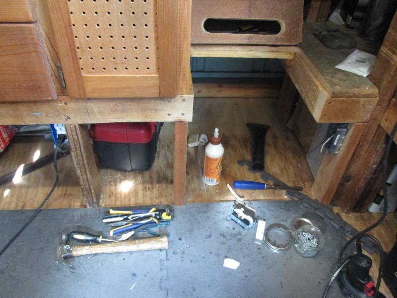
1st the receptacle. Wanted a metal box with round corners but it stuck out too far. I chiseled out about 3/4" so box doesn't protrude as far.
Board holes thru all bench members to route romex. Ready to just drop a line from receptacle above. Realized at 13 amps too much with everything else that might be in use on that line. err...
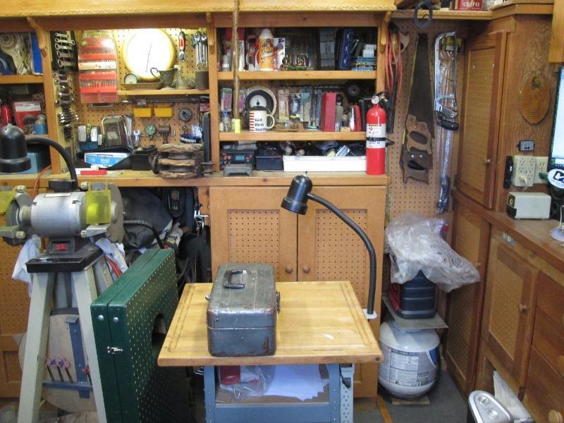
Decided to tap 20 amp line on other side of shop, it feeds drill press (just out of view to left) then a plug for grinder on rear bench where orange cord is. There's a 2" space behind upper shelves and wall and existing hole thru pegboard where line comes in. Be simple enough to run from last grinder receptacle behind shelf pegboard. Ill have to cross front of pegboard where hand saws are to enter under front work bench then straight shot to new compressor receptacle...
2 hours later, pushing wire 6' proved impossible, ended up removing section of pegboard. Pulled wire to front work bench and put all this back together. Better with romex behind but this sure wasn't planned.
Boring holes/stapling as I went got the romex over to compressor- I am literally 6" short of reaching receptacle! Remanent from 25' roll, about 22 feet, should have been enough though I knew close. No way, no how, for any reason am I pulling a new wire.
Next day- I was going to add junction box and extend romex but decided better to pull line back and add another receptacle before then run from it. Dropped line, added box/receptacle, then run to compressor receptacle. Worked out as I can use second receptacle for heater.
So 20 minute receptacle addition took a good 8 hours. Now that its done.. works slick just reach down and flick the switch. Added pilot light.
2nd tieing bottom of added leg.
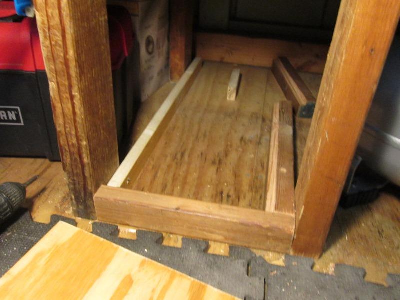
Using 2x2 between new and old legs to support side to side. Front to back using another 2x2. screwed to each other and floor.
Add cut 1x2 on opposite side. 2x2s are cut with notch for planned plywood to set flush.
Full depth 1/4" plywood top is nailed to sub structure. Only lost 1 1/2" storage height. Making a door to match upper.
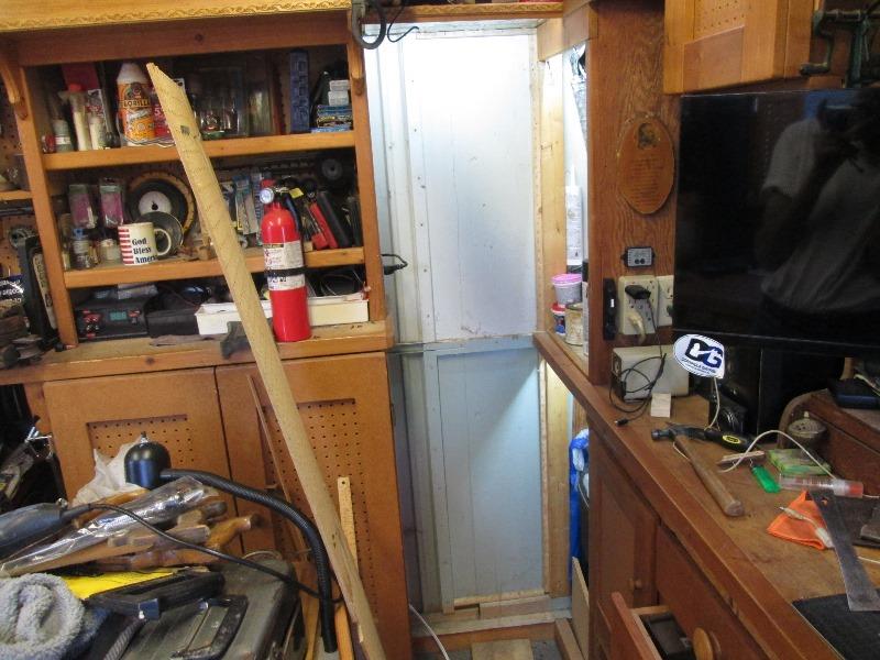
Door
Door..jury still out. Because I used 2x2 for bottom, door is close to floor- hit with boot, constantly. I have 4 other doors but they have 2x4 toe board. Other than that this just looks goofy. Easy enough to replace the 2" with 4" toe board but then Id need to lift what ever is inside over. The door would need to be taken apart and cut shorter but pretty sure it would have to be cut apart. Could try to just move up, use a fake toe board riser-piece of 2x2 that just sits in
What I ended up doing after hee hawing around with options was to unmount door and not hinging. If door was inset I wouldn't need to bother with toe board height. However it would need to be inset at least an inch to be out of the way. I looked at hinges that would work but expensive. Standard inset hinges would work but door would only open 90° and tool box wouldn't clear.
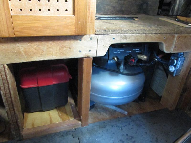
My solution was nixing hinges, just lift out door.
Mounted stop blocks at bottom and 2 magnetic catches at top ( above tool box height). Trim door to fit inside
Simple, door back out the way. Boxed in the new plug on left
All in all pretty happy although just using and storing the compressor ended up a 3 day on/off exercise. Not planned but resultant switch receptacle for compressor, a floor level receptacle that's tucked back out the way -both on 20 amp circuit. Useable 'hidden' place for storage. Air quick coupler at bench... Kind of fun...Just amazing what was intended just sliding under bench and what i ended up being doing to accomplish...
Yet to do is add handle to new door.
Drain relocation
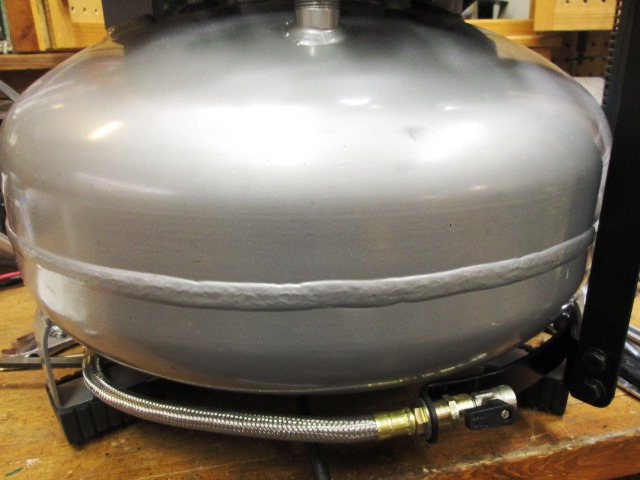
All I can address is valve on side. I am going to add elbow and nipple to relocate drain valve toward front.
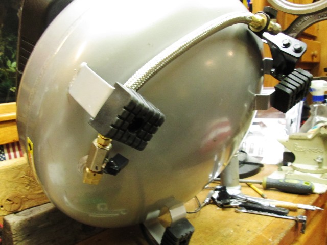
And done. Looking at relocating drain stumbled on these flexible hose kits. Comes with elbow, hose valve and 1/4x3/8 adapter.

Still needs to be pulled out & tilted to drain water but on the side didn't make any easier. I mounted with the included valve threaded into elbow and used existing valve at end of hose. This allow shutting off hose should there be a problem. Bent a piece of flat bar to hold end of hose, bolted to previous quick coupler bolting.
That was easy. Look at making a platform to sit compressor on that holds at needed angle to drain without me holding it.
Likely replace cut in/out pressure valve to lower tank pressure. I don't need the volume that 175# offers, I'd rather it ran more. Seriously think as this uses simple screw in switch is to add tee and 2nd lower switch. Use a SPDT switch to select which pressure switch controls. Either 175# for framing nailer or general outside use, 125# for in shop use. hmmm
Add selectable lower pressure switch
So without hesitation ordered an 1/8" NPT 90on/120off psi pressure switch. This may be too low and compressor runs excessively and have to replace but volume used in shop will be minimal so trying.
Opened up compressor and removed the 175# switch. Its 1 1/8" hex. Then threaded in a 1/8" tee using 1/8x 1 1/2" long nipple. To the side outlet of tee, threaded in factory 175# switch. To the end where new switch will go temporarily used a 1/8" plug. Easy enough but thinking I should have used an ell to place switch vertically, less likely for debris to foul, probably revisit.
Now to wire
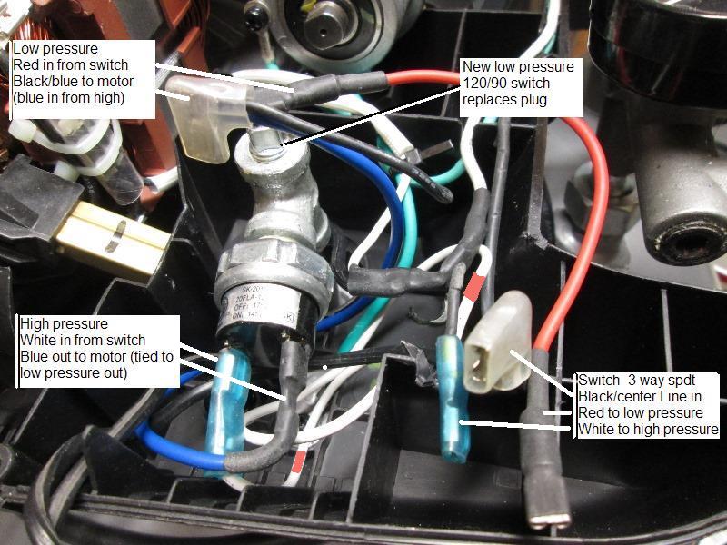 Incoming line that went to pressure switch now goes to center of new 3 way rocker switch. Wire from one side of rocker switch goes to high pressure switch, the other to low pressure switch. Selectable as to which pressure switch controls, high or low.
.
Carve top of cover to mount switch. Placed on top half of cover for visibility, would have been a lot easier to wire on lower half but for use better.
Made couple of labels, rocker switch is rated for the load but do not think a good idea to switch when hot. Waiting on pressure switch...
No updates/pictures-but switch arrived and installed. Replaced plug in tee with new switch, connected all wires- Works slick. Done
Back to work...
Back to top of page
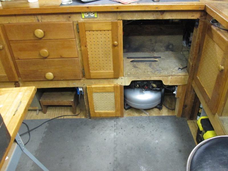
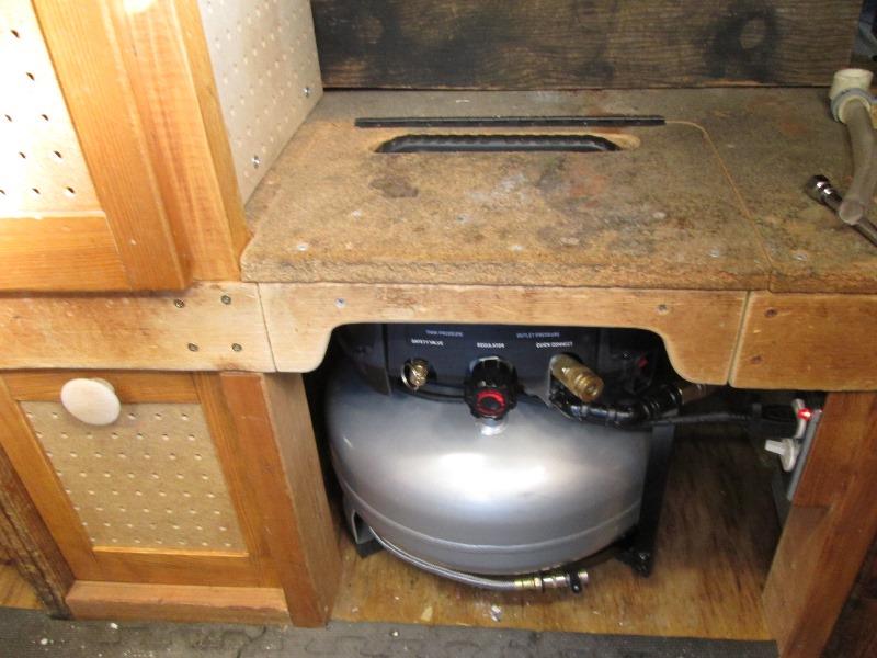
Add window to see gauge & power on pilot
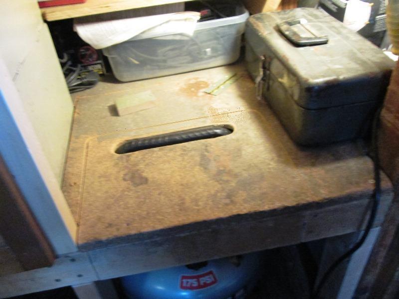
Bit later and nothing better to do decided to open shelf to 'see' the gauges and the pilot light. Idea originally was to simply flip up the shelf when using compressor, to see the gauges, setting max PSI etc. However in usage it got old, small tool box lives on this shelf that needed to be moved and accessories on the side pegboard usually got knocked off.
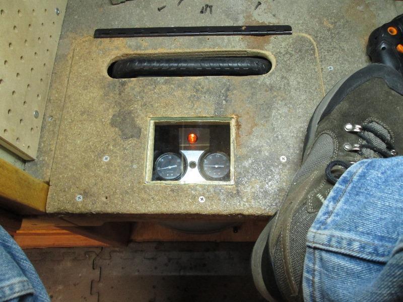
Remove shelf, cut approx 3 1/2"x 4" hole. Then cut a piece of 1/4" glass to 4" x 4 1/2". Traced glass center over hole and cut recess 1/4" deep for glass to set flush. Nice! Pilot and gauges visible.
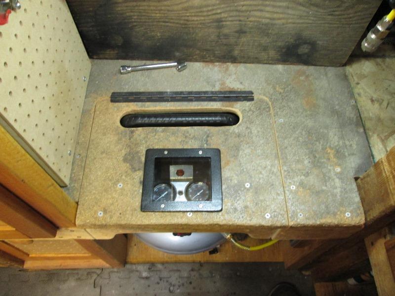 Welded up frame using 1/8"x 1/2" flat bar, counter bore for screws and mounted. About this time realized I should had set glass a little deeper and added another recess for frame so it would be flush. Decided to ignore. Later probably resurface top of shelf, pretty chewed up with some hardboard or maybe linoleum.
Hose reel, 3rd Q/C...
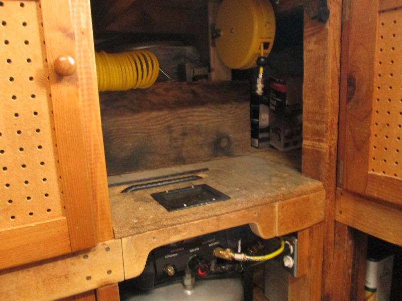
Instead I installed cheap hose reel.
New window allows much needed light under shelf- bonus. I need to turn fitting like other outlet for new hose reel so it can stay plugged in. However would put hose in front of on/off switch. Hmm think a 45° ell between hose end and male quick coupler would work-details.
Addressed quick coupler for new hose reel. Was going to plumb top coupler so it pointed to side but noted plug on bottom of manifold. Simply added a 3rd quick coupler for the hose reel to plug into.
I say simply, but to thread on the ell I had to remove the manifold. Breaking the large manifold nut on pipe welded to tank took some effort. Remove support for middle coupler.. Entire manifold with gauges, pop-off, regulator and quick couplers lifts off. The smaller pipe from manifold inserts into the pipe on tank, basically has a large ferrule that seals with the large nut.
All about convenience.
And all about appearance...

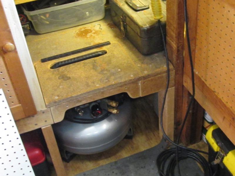
Last few mods all I could see was how grodie the surface of the particle board (foot well) was. Outer edge breaking up from years of boot resting. Decided to add some aluminum edging. Looking thru material found this old linoleum. Perfect. 1'8" thick - well covers the dirt, coffee and other mysterious stuff. I cut out the linoleum for site window frame so its now flush with linoleum surface.
Went ahead and did the other foot rest.
Back to Our shops tool mods section