FMS Atlas 6x6
6 wheel drive ready to run,
everything but 4 AAA batteries.
Red or blue truck ~$1401x 1:18 Atlas 6X6 Crawler
1x Transmitter
1x 7.4V 600mA Battery
1x USB Charging Cable
1x Wheel adjuster
6x spare spring
1x User Manual
Simple inexpensive 1/18 scale rc truck. Was relatively inexpensive-just wanted something small/cheap and simple to play with in the yard but the 6x6 really intrigued me. Out of the box this ready to run RC truck is a blast. It certainly isn't a crawler (by 1/10 scale standards) and soon realized small scale is a whole different ball game.
Kinda new what I was getting into but few issues led me into NOT what was planned, primarily modifications. Aftermarket support is somewhat limited. There a several YouTube videos that help a lot.
In order of occurrence, more or less, mods to 6x6. I didn't get pics of all. Doubtful if helpful but might help toward a direction. Really just documenting for myself. This, though minor mods to perform better, also this is more of a model as far as making it look 'period'.Though trying to create a bit more realistic look this atlas only vaguely resembles a WWII Dodge wc truck or later power wagon. Still, it has the 'look' Just time in the shop...
DISCLAIMER:I'm putting everything about this 6x6 on this one page so it's very long, a bit disjointed
Index:
1st Replace ESC & receiver
2nd Rewire headlight w/plug
3rd Paint/Weather body
4th Larger 62mm tires
5th Move center axle for tire clearance
6th Modify bed- rack, bed side rails, 6th B-modify again for tire clearance
7th New oil shocks
8th Modify bed again for new shocks
9th Replace Transmission with metal gears version, other issues
10th Body lift, bumper mod- front tire clearance, stays open
11th Replace 'tool' box with Dynamite crate
12th Extend bed to rear
13th Make rear bumper, relocate tail lights
14th Relocate middle axle shocks to rear of axle
15th Replace factory front bumper with FCX24 front bumper
So it begins
That said, as much fun as I was having I need to address some things.
1st
Low speed crawl control is almost nil. An obstacle that stops car you feed more throttle until it finally lurches forward. Just no low end grunt. That and seriously LOUD whine. Most recommend changing out the ESC. Which did help a lot. The Atlas uses a combo speed controller/receiver unit. So to replace ESC you also need to change receiver. Following recommendations of others cheapest route....
Electronic speed control: Hobbywing Quicrun 1060 ESC
Receiver: Turbo racing 4 channel receiver (RX41)
These work well and pair to stock radio. Better throttle control, less whine. Motor runs cooler. however NOT a direct bolt in. As plugs do not match leads of old receiver/ESC must be transferred to new ESC. So some soldering required. (https://www.youtube.com/watch?v=pGEEo0azJVo link to user performing swap...)
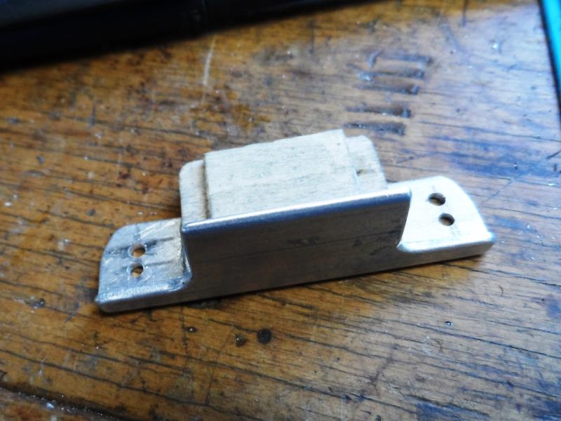
To mount new ESC and receiver I attached (high strength 3m moulding tape) a small piece of aluminum to stock receiver plate. This extends enough to mount both new the ESC and receiver up front.
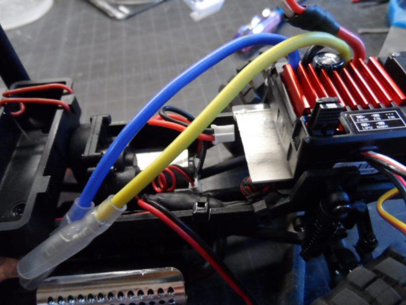
ESC mounted
Old leads/plugs solder to new ESC leads. Except the difference in wire size, minor. Receiver mounted, bundled wires. I'll mention stock receiver has 2 light output leads, I soldered together so if in future want to add something have a plug all ready.
Vastly improved low throttle control over obstacles, way quieter.
Back to top of this page
2nd
Wire headlights together with one lead out. Cut an old servo extension lead, solder male half to lead from head lights. Separated headlight leads from bundled light wires removed one and soldered on female end to remaining 2 wires to feed headlights. Tail light wires(2 pair) still run to rear but now I can unplug headlights to remove body.
Unsure why the lights are run with separate wires to each led.
Back to top of this page
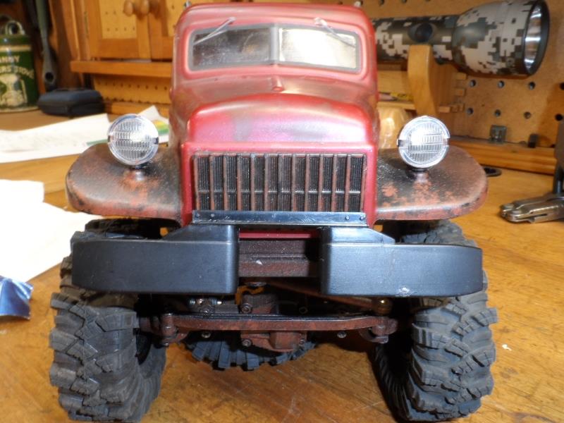
3rd
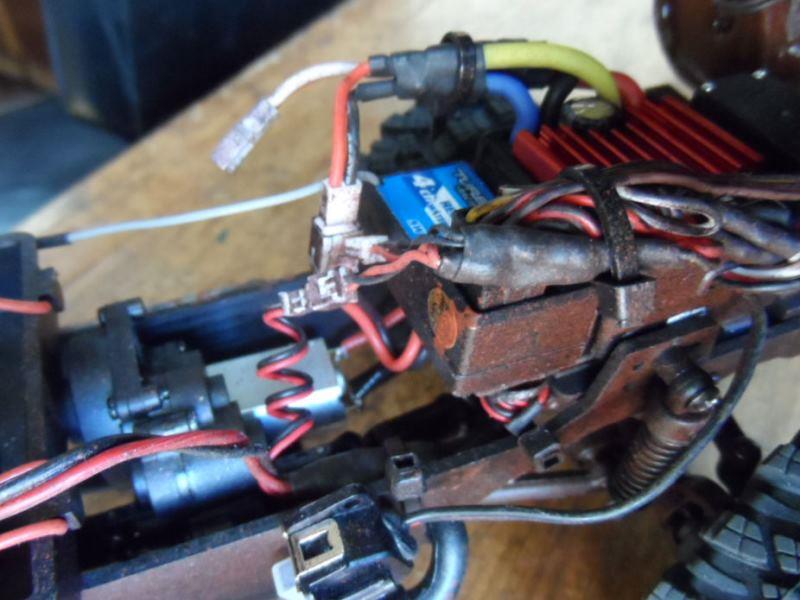
Paint and details... Tried to give an old rusty weathered look. Chassis I air brushed dark brown with alternating mist coats of flat black and rust color. Went back with a brush and minor washing/streaking with rust/brown.
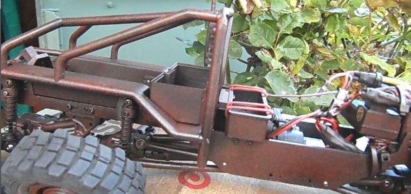
Looks ok, my 1st attempt at 'patina'.
The body comes painted color on the inside with a flat clear on exterior. the fenders are painted black on outside. I tried using brush to patina-total fail. I end up sanding thru body inside where I wanted rust/discoloration then repainting inside with dark brown that shows thru.
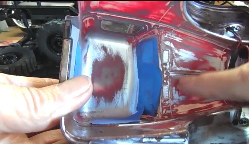
When sanding feather out and from outside the new color will fade in to existing color.
Amazed me, it looks like paint actually worn off with age as show on left rear quarter panel.
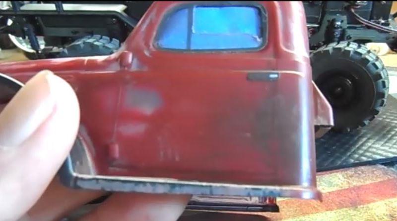
Discovered the Atlas 6x6 lettering on the hood that I wanted to remove is actually outside. So I wet sanded outside, 600-800 I think, but it removed the lettering. Because its sanded even, though clear coat removed, its still matt.
The fenders I washed with very thin paint, then add some streaking/rust edges.
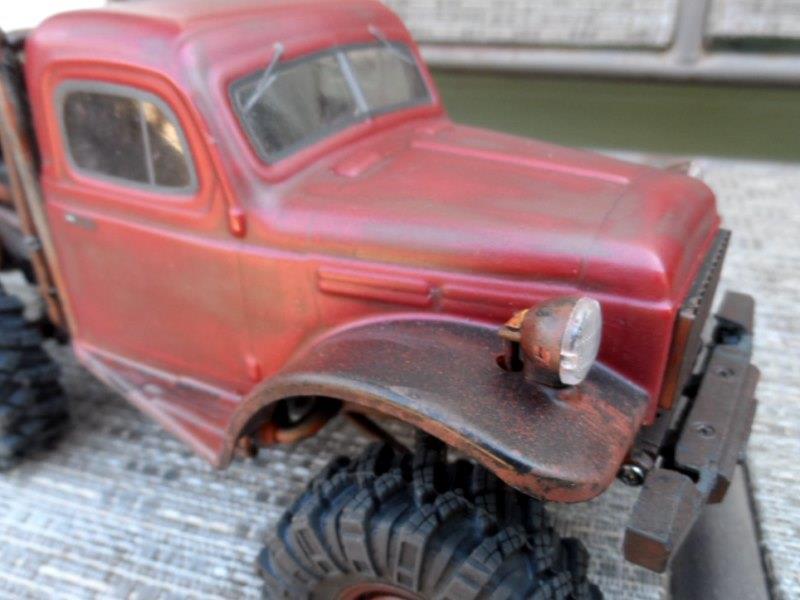
Hard to photo due to reflections, actually looks better in person (but still hacked)
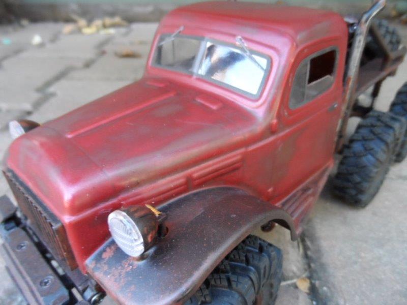
All in all pretty happy. Though wished I could have done better still looks like its been sitting in a field for 40 years.
Back to top of this page
4th
Was the tires. Supplied tires look cool but do not really work. I opted to change the 55mm diameter to 62mm 'mud terrain' from makefire (https://www.amazon.com/dp/B0BKZ3HR1B).
Injora makes similar tire that may be sticker but as I needed to buy 8 tires went cheaper. They work ok.
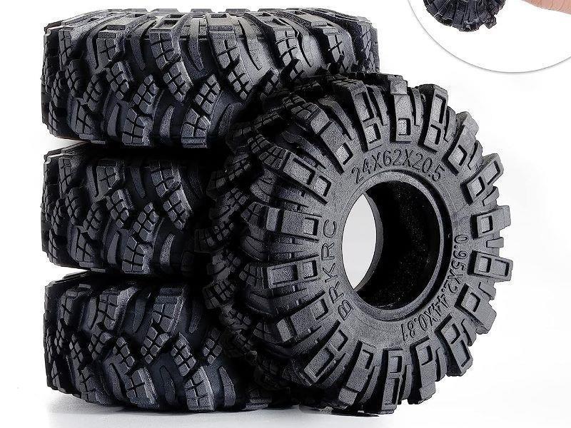
Issue however new tires being larger they touch each other in rear. Which I knew watching several videos. Not too difficult to solve once parts identified. It involves moving rear axle to gain clearance. But I'll address that last. My 'fix' to run larger tires involved a whole lot more which I'll get back to.
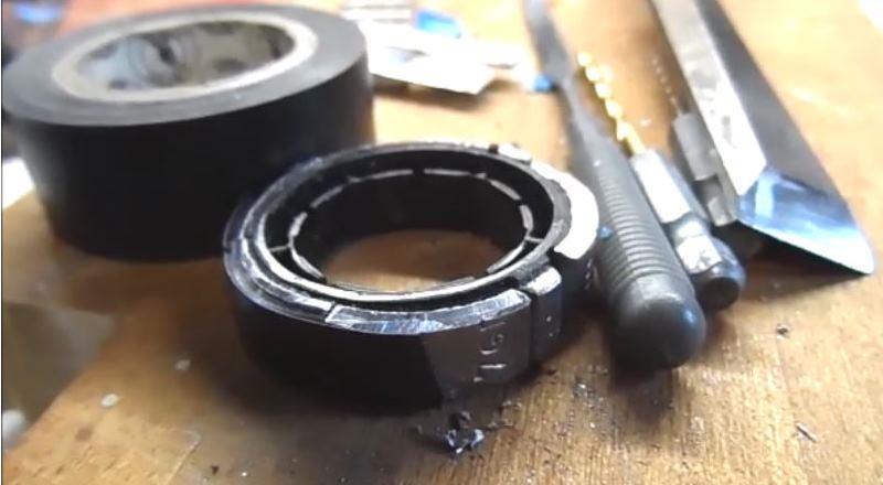
Meantime mounted and weighted. Used chisel to cut self stick weights to 1.0 wheel width. Pliers to curve flat weight to set on round wheel. Wrapped with electrical tape to ensure dont come loose. Quite heavy though haven't weighed. Old school.
Back to top of this page
5th
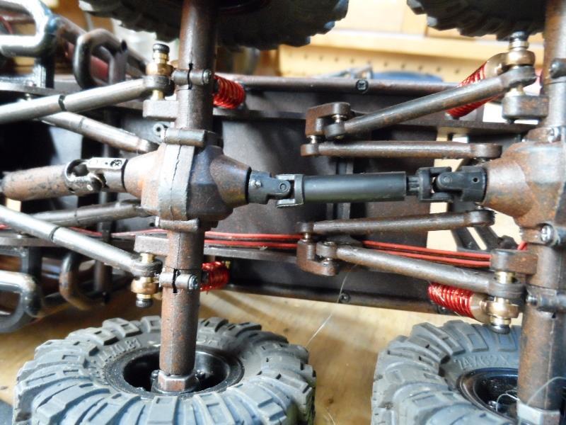
Increasing distance between rear axles for the larger tires.
Most, or all I've seen, move the back axle back. Just need a longer driveline and longer links or you can just move the attachment block on frame and use/keep stock links.
I decided I wanted to move the center axle forward instead to increase distance between rear axles, this also allows decreasing distance from front axle. My reasoning was to keep same overall wheel base length and minimize high centering while allowing for larger tires. Still need a longer rear driveline. Center driveline needs to be shortened (center driveline could stand to be collapsed a bit-its really at its extended length). I trimmed a bit off male end and reused center driveline with much more engagement.
I'll note I moved axle 1/2". 3/8" would have been plenty with better shock angle, could redo but maybe later....
On the links...due to the way upper links attach to skid/motor plate I decided to cut and shorten stock links. Drill and tap to reassemble with all thread.
Removing all 4 I cut out a 1/2" from each. Then on drill press I center drilled halves about 5/8" deep. Ran a 2-56 tap. Cut about 1" lengths of 2-56 all thread to screw back together.
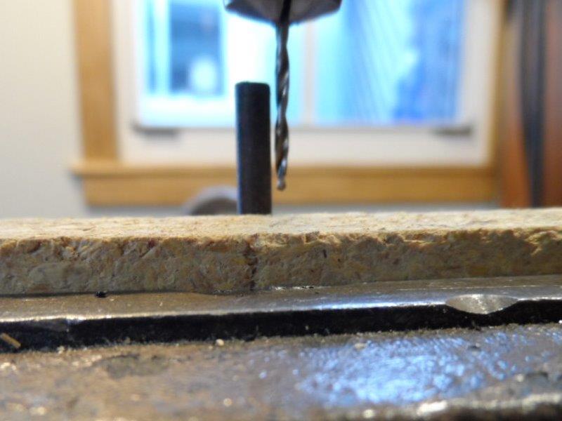
Luckily I have a drill press allowing to align link halves square to drill bit. Still a bit tricky keeping hole centered in link.
Managed to do all 8 halves without drilling thru sides of link, only one is off center. Just luck but it worked. . I've since picked a set of stock links and will try again on off centered half. Likely will sleeve lower links with aluminum tube
On the rear driveline I used Axial AXI31611 SCX24 set to fab. The D hole isn't quite the same as FMS but a little finessing it will work.
I did need to open diff to hold pinion for insertion into driveline ends. Screwed together links allowed adjusting pinion angle.
Bit of a pain, caused some other issues with truck bed, shock clearance but worth it (now that its done) IMO.
More than enough room for tires. 3/8" between rear tires, with wheel overall base same at ~8 1/2" but 2 13/16" middle axle to rear axle, 5 11/16" middle to front axle.
Back to top of this page
6th
Use the pieces to extend the side rails. Also cut out center of rack so back window more exposed.
Put the spare back on because the bed doesn't go all the way back. In the future likely get some plastic and extend bed to the rear and dump spare.Looks way better in my opinion.
6th B second time
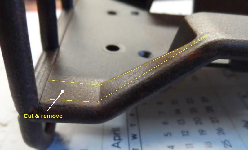
The side rails dip down and out at front. Tires were hitting hard.
Material removed
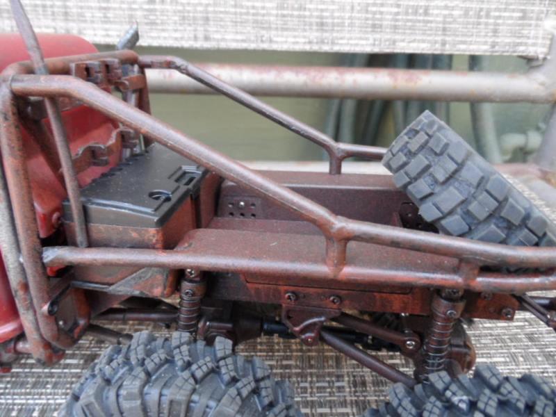
heat and straiten pipe to match ...
Then kick out ends to reattach to roll bar. Re tap ends and run screws thru roll bar into ends of rails. I also glued the bed floor to roll bar at front edge
The sides of tool box close off the gap. Cameras dont lie but they do exaggerate, looking down the rails are as wide as bed floor an all but against tool box. Not something most would need to address.
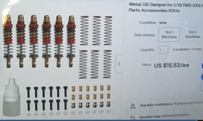
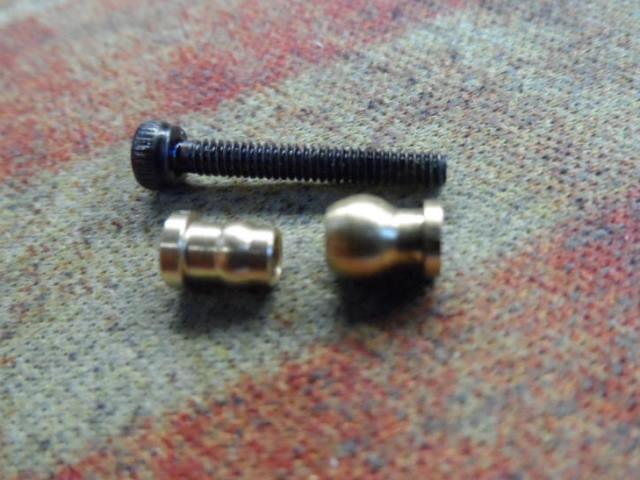
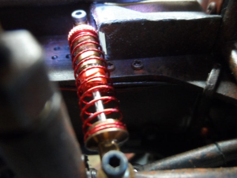
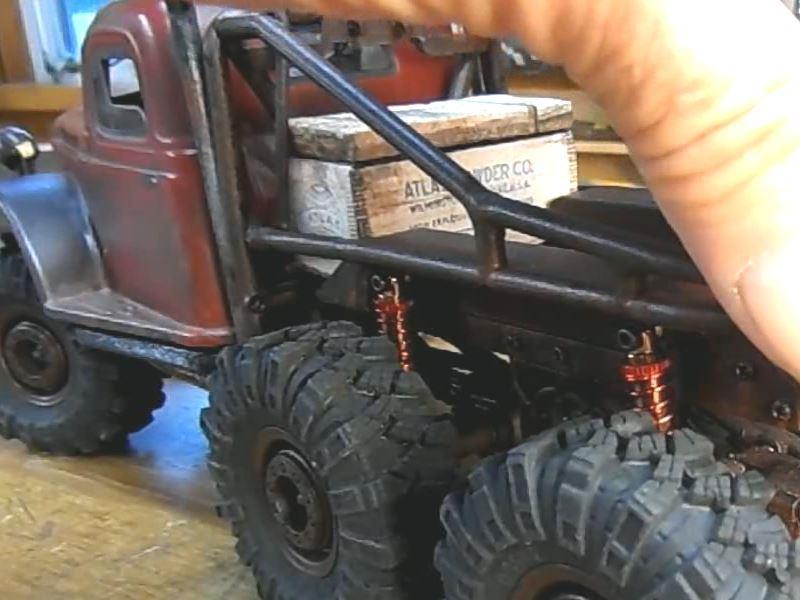
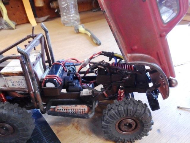
7th Shocks
Found a set (6) of adjustable aluminum oil shocks for $15 (shown above). Same length but oil filled. Really got rid of the boingy bounce and jiggle.
Includes hardware to install to suit.
On the bottom ends need to replace stock double ball with 2 pieces from kit. Upper ends use included ball sleeve, nice as it gets rid of screw mount that you cant tighten.
Have to reuse the stock upper spacers as shocks will hit frame (like stock).
I'll note on the front upper mounts if running larger tires cant use the stock spacers and top mount needs to be rotated forward otherwise tires will grab mount screw. I discovered after popping driveline.
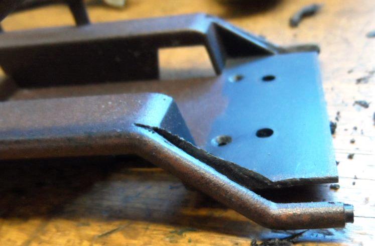
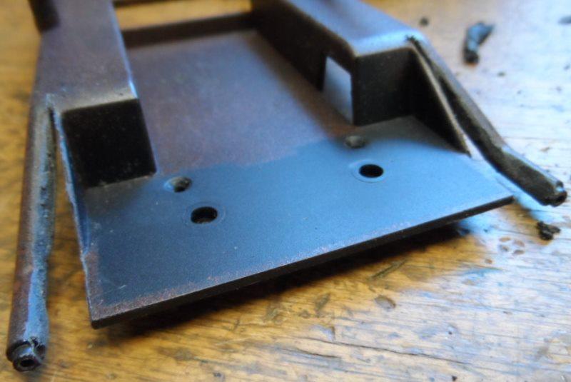
8th third time
Stock shocks cleared but new shocks a bit larger diameter. Due to axle moved forward top of shock already at max forward location and cant be rotated back.
In the distant future I need to get front half of stock axle housing to replace the rear half so I can relocate the shock behind center axle. This would put it back to vertical. (LATER shocks relocated to rear of axle see index or Section14
For now to allow shock movement I cut out the front of bed 'fenders'.
allows shock movement
9th Replace Transmission
Right off the batt managed to strip gear in trans. You can get metal replacement gears for about $8, I found the Hobbyplus CR18 trans (#240257) for the 6x6 conqueror offers a complete direct bolt in stock transmission with metal gears WITH motor for $18 from MotionRC.com. Actually being virtually the same, many parts from the HP Conqueror 6x6 are interchangeable. The FMS parts are usually cheaper but harder to find.
Later again...Having a hard time keeping this running. Popped a drive line due to top of front tire hitting top shock screw, locked wheel. Moved shock which fixed. Then later burnt up a motor. Even with replaced ESC the motor gets hot, like 130�. Replaced. One issue is wheel weights. I've added quite a bit and I think I need to remove some. Seriously looking at and probably will replace all the axles at some point (if I want to continue driving). ...to be determined .
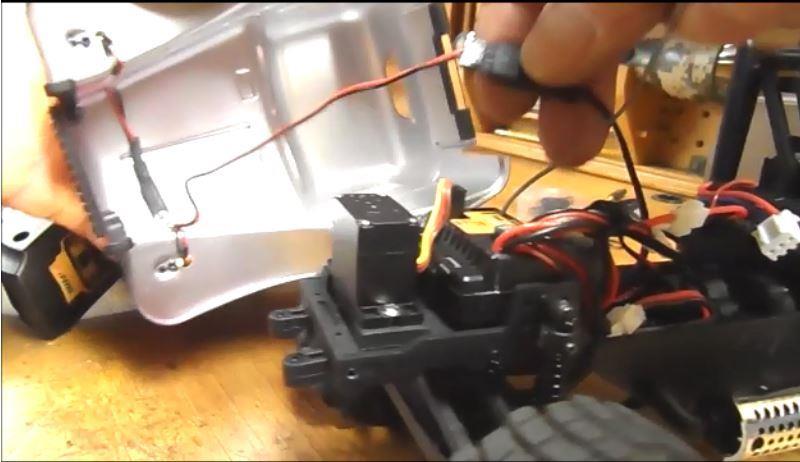
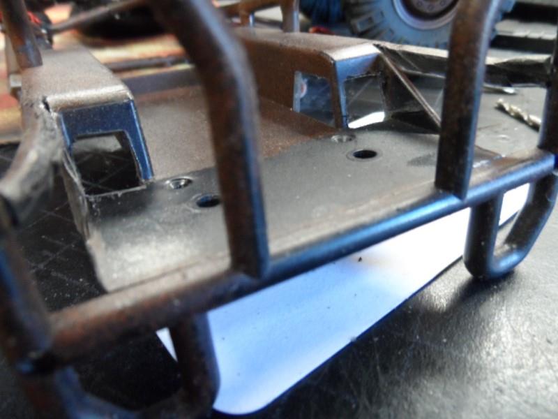
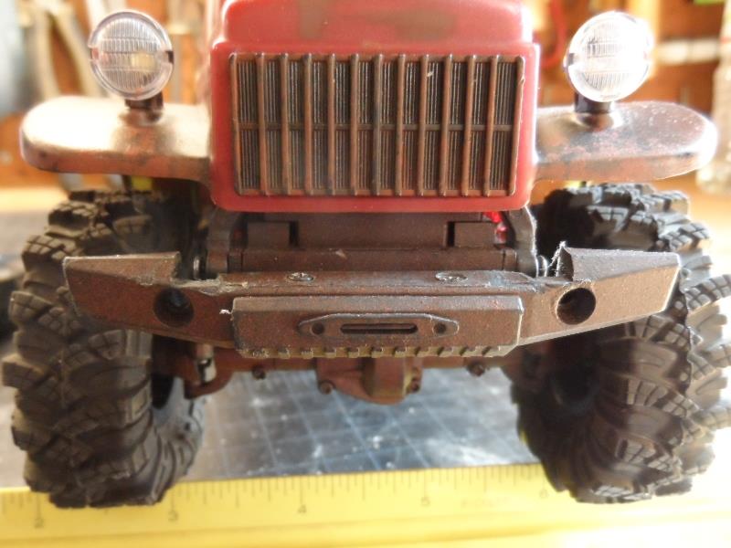
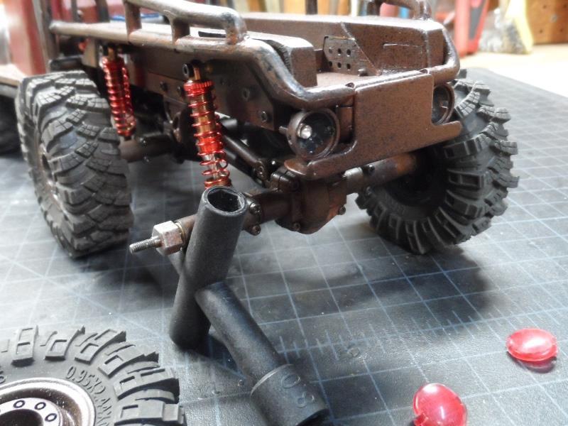
10th Body lift
I lifted the body about 1/4" and lowered bumper 1/8". More tire clearance and allows body to stay open when tilted.
Glued 1/4" metal rod to rear magnet.
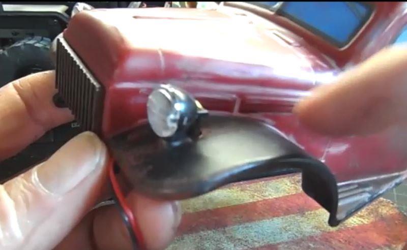
On the front I removed front grill, slotted the 4 holes so grill could be mounted upside down which relocates the pivot arms lifting body.
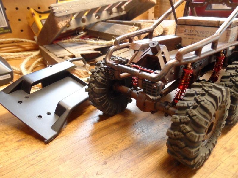
Removed the overrider bar. Mounted bumper mounts upside down to drop, trimmed back of bumper ends for tire clearance. Notched for body pivot arms.Many just delete bumper The included front bumper is plain silly in my opinion, just doesn't fit truck.
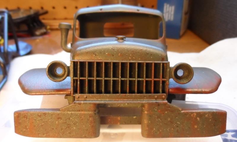
What I'm going to do is replace with bumper from FCX24.
Front of FCX24 and bumper, mimics actual Dodge WC bumper. If this bumper can be mounted to the Atlas hinging with body, would be higher, tighter to body. A lot better approach angle/clearance and just looks correct
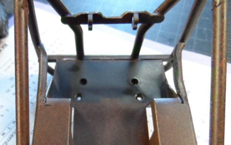
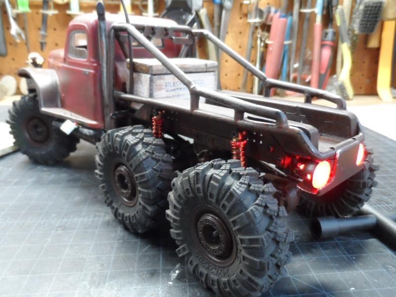
11th
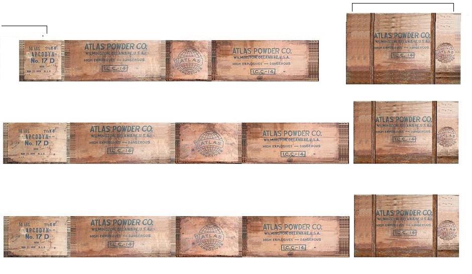
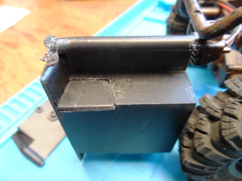
meantime I replaced the 'tool' box. Just appearance but found the stock 'tool' box silly. Found several vendors selling antique wooden crates "Atlas Powder Co." boxes. Used windows paint to skew pictures square then scaled to fit.
Print Scaling pictures in windows is ah..difficult, top row was final attempt.
I folded up a card board box, piece of lattice for top. Glued the pictures to box, when gluing is when I realized the coincidence- "Atlas Powder Co."
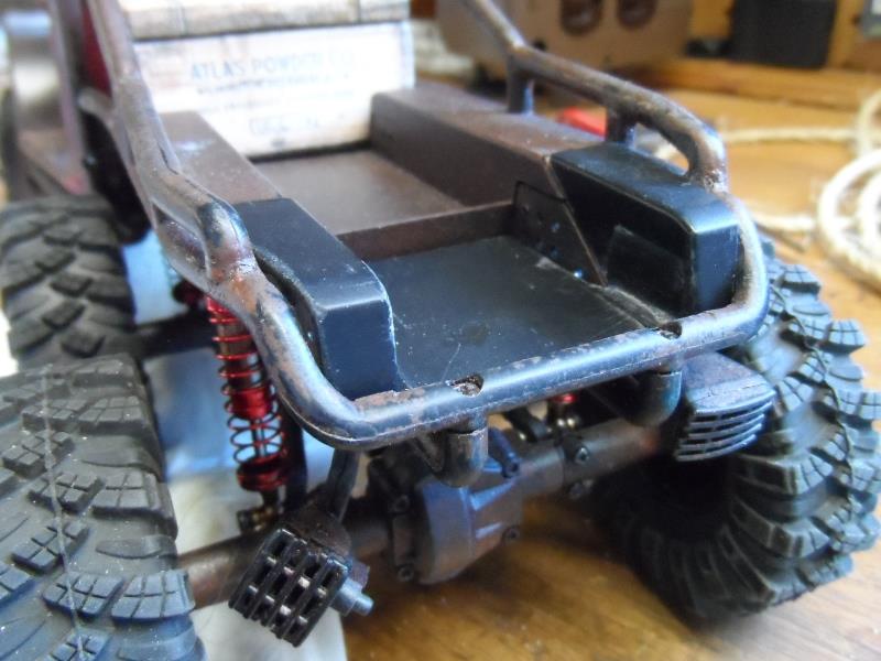
Top of box is notched to fit against roll bar and accessory mounts. Its really snug so no other means to attach was needed .Looks better IMO than the included 'tool' box
Kinda gives the funny truck platform a purpose...hauling dynamite.
12th
Speaking of bed, even though I'm not sure how I'm proceeding on the rig as far as axles, rear steer and cooking motors I really want to FIX the bed. Or get rid of the open area at rear, nix the spare tire carrier extending bed all the way to rear.
I had bought a spare bed while back to try to cut and extend the bed. Not sure how, just cutting as I go. Did decide to flip new bed, use the front as the rear to extend back of existing bed as the fenders go all the way down.
Made cardboard pattern, 1st cut at back of fenders.
Then cut at floor length where it will butt to existing floor. Next is cut sides to match profile of frame side rails..But the angle will be almost into the cutout.
Cut out some scrap to fill and glue. Cutting the angles to match frame is going to be difficult. Cannot check until fenders are trimmed to match narrowing of the roll bar.
I've really gone as far as I can without this becoming a complete failure, maybe 25% of success. ...waiting for glue to dry.
Well...I had intended to fully document extending rear of bed. But it took forever. Mostly just carving a little, fit, carve some more...
Finally got it to fit, not perfect but ok...
Currently bed just sets there, pretty snug. I had glued a strip to new bed floor that slips under original. Bit later but shows 2 screws thru frame to keep section in temporarily. Once everything is finished Ill cut out the raised vertical section at end of old bed and glue sections together to make bed floor continuous.
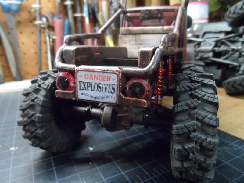
13th
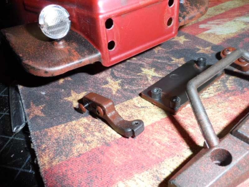
Now to remount lights, make rear bumper..
Making bumper using 1/2x3/4 aluminum angle. Cut/drilled for taillight housings. To mount made spacers to drop bumper down from the 2 frame horns (space for taillights) with a piece between to locate. 2 screws from underneath go thru all into frame horns.
Getting ready to mount the taillights plan changed
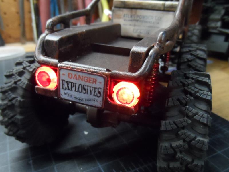
The louvered taillights on flat bumper looks like grill from 80s compact car -something is just off. While nice lights I have 2 round lights that look more 'period'.
Got bed painted- pretty close match. The light lenses (spare headlights) used red nail polish inside to color red when off. Not enough room to pop lenses on err...take apart to assemble.
hmm maybe pintle hook or couple of D rings...I Like it, few details, a little touch up paint, block the leaking light, attach the new bed, done.
Or maybe a sign...added some LED light blocking film until I solder in a larger resistor.
Kind of what I was hoping for, and was kind of fun doing. Was it worth it - no, well yes now that its done. Ideas are easy-executing different story so take what we get. But I dont hate it like the stock bed.
Issue now is adding rear steer, used up all the easy options for mounting servo getting the bed extended and rear bumper. No extra room between top of axle under bed for axle mount. Bed is 3/8"+ thick at rear so direct chassis mounted not option. Possibly with some linkage, servo hub shaft extension...some thought required. As limited as rear steer will be with center fixed axle it would still help. Its just coming up with solution that 'might' work to pursue. TBD
Maybe when/if I replace axles. Worm gears and reduction of SCX24 axles would be real nice-FCX24 axles due to width and portals good option. But 75-100 bucks makes either really a pipe dream at present. Well see how old breaking stuff gets....
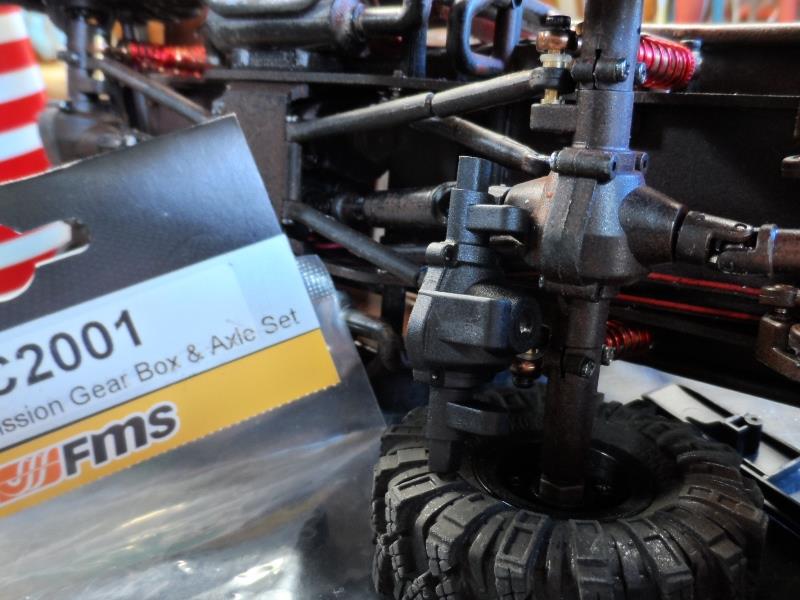
14th Relocate middle axle shocks behind axle. Previous mods allowed new shocks to work but the travel of middle axle was different than rear axle, angle was wrong and no adjustability.
Ordered C2001 axle housing set. Only need one half, but for $3.50 set includes all 6 center axle housings and complete trans case.
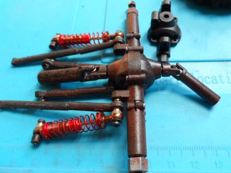
Removed middle axle (shown upside down). Remove wheel hex and axle pin. Unscrew and slide axle housing ends off of center section. Unscrew back half and replace with a new front half that has shock mounts.
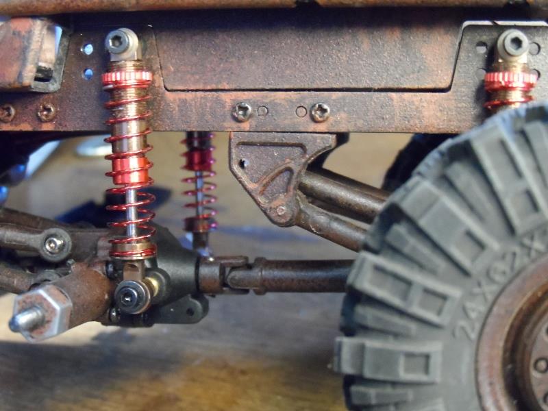
The new half is same as the front half but they fit together, no modification required, just flip upside down for ring gear orientation. Only issue is both halves have clearance holes for screws to pass. So (4) larger M2 x 8mm screws needed to thread. I didn't have any single ball so reused stock double ball for the link side. Moved link and shock hardware to rear half.
Much better shock angle with regained adjustability, same travel as rear axle. Should have done this instead my original bed trimming.
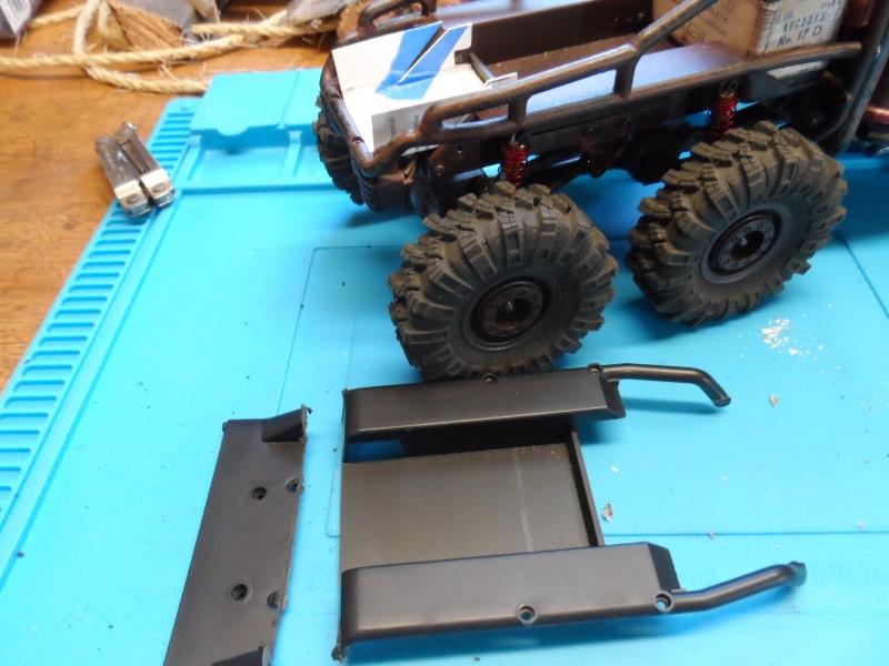
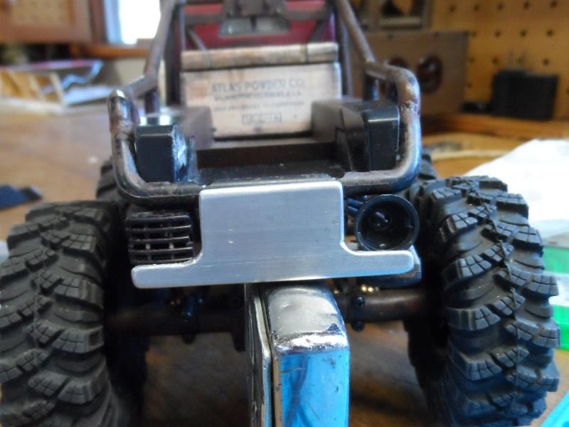
15th Even after all the mods to make work replaced the IMO Atlas goofy bumper with an FCX24 bumper that mimics Dodge WC bumper. Even though this bumper would be for a truck with winch, the early Dodge winch sat behind bumper and bumper protruded out quite a bit.
Obviously not room (or practical) so mounting as high & tight to body as I can get. Don't imagine for a second that anyone would do this but what & how.
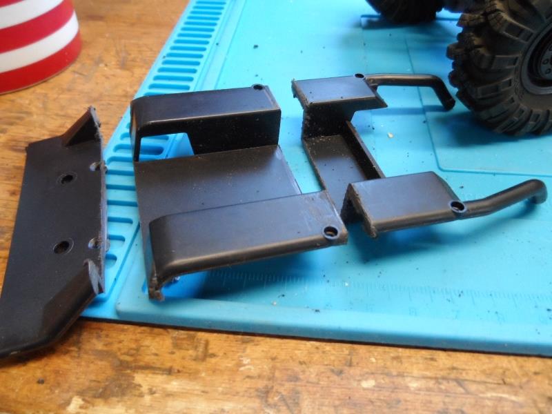
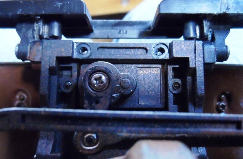
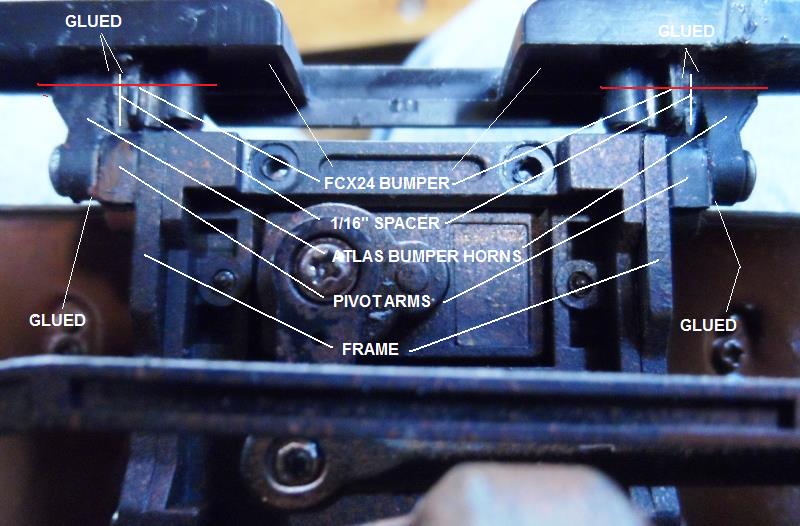
Well nothing about the FCX24 bumper lends itself to mounting on th Atlas. What I did was use Atlas bumper horns, glued to the pivot arms and to the bumper mounts on back of bumper. Didn't use FCX bumper bracket. So bumper is attached to the body pivot arms. The horns are glued at angle to raise and move bumper up.
1st glued thin pieces of plastic to outside of bumper mounts to fill gap between the horns and bumper mounts. Bumper mounts are a tad narrower than inside of frame horns when in place). Then applied glue to frame horns and bumper mounts, to place ran a screw thru frame horns going thru pivot arms to clamp in place to the frame. Adjusted the horns at slight angle to get bumper square to body and height.
Clears as mud...red line is added permanent screw
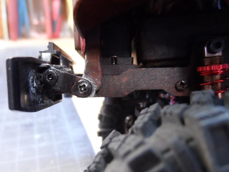
Once dry unscrewed bumper with glued horns from pivot arms.
To glue the horns & bumper to pivot arms used the pivot screws (coated with thin layer of grease) to clamp horns to pivot arms. Let it set and slightly loosen and re-tighten the pivot screws, trying to ensure they dont get bonded or body wont pivot.
While the bumper to horn connections are secure being screwed and glued the connection of horns to pivot arms is solely relying on glue as the pivot screw needs to be loosened to pivot body. That's where I see impact may break bond and the bumper rotates. Likely will add a brace from top of bumper to plastic radiator/grill or something.
Not that this is even close to a scaled WC truck but looks better to me.
Nuff for now
Back to top of this page
Back to Ourelkhorn Camper Modifications page
180
Roll cage and bed, revisited a few times. 1st for appearance-removal of some of the cage, then mod bed for tire clearance, then again for new shock clearance (due to moving middle axle).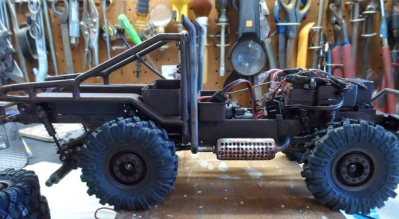 Original cut of roll bars, extended side rails.
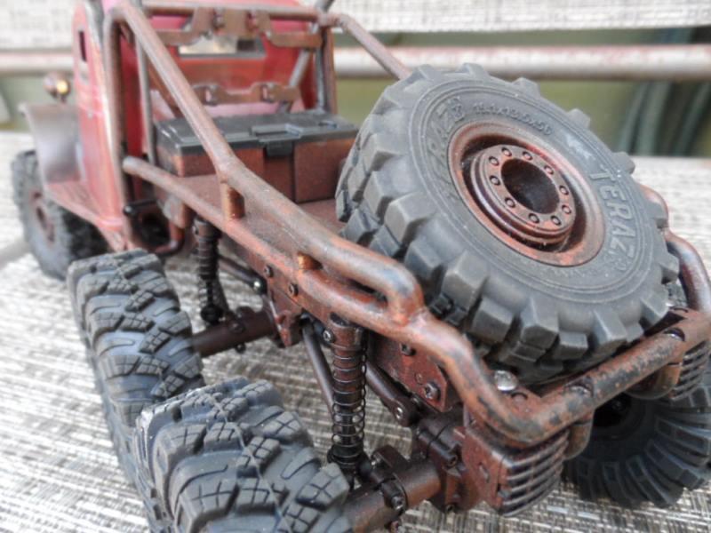
Quite a bit later, if you noticed, I had to revisit rack once new tires were mounted and suspension modified to run the larger tires. 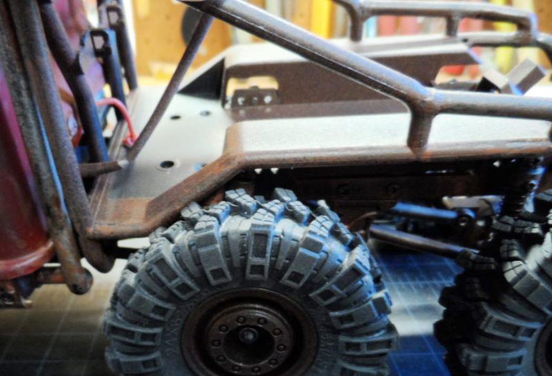
Modify bed for new shock clearance. Found some oil shocks but were rubbing bed. 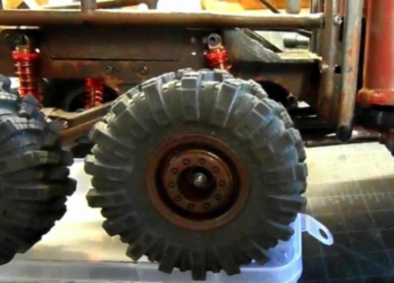
). Will defeat cutting bed but axle rests about 3/16" higher and goes up higher than others due to shock angle.
. (update managed to install FMX24 bumper see index or Section15)
As the stock tail light mounts interfered with bed going all the way down I ended up cutting them off. I'll make a bumper to reattach..
The new shocks use different hard ware to mount them and links. Even though links wont be relocated, the screws and all brass balls will be moved to rear to keep shock offset. Front will need a pair of ball mounts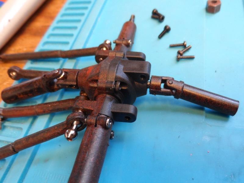
Note the new axle half mounted upside down has link mount hanging down. IF trimming it off desired note that it is hollow, cut to much and inside of case will be open to gears. 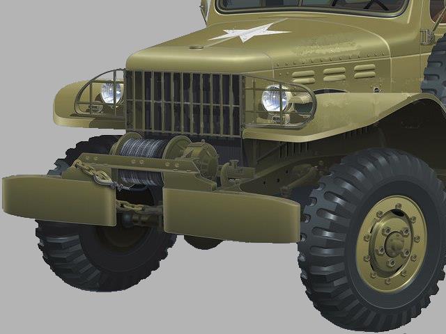
 ..and it still works.
Back to RC crawler index page