Adding watt meter to inverter
After a recent discussion about TVs and whether to run direct 12v (cutting off supplied inverter "brick") or thru inverter, due to self power consumption of inverter and the waste of inverting 12v to AC then back again prompted me to consider adding a watt meter between inverter and battery. I know our current 12v use thru the inverter is minimal. Our recent swap to an lcd with built in DVD, even when running added sound bar is WAY less than our previous TV, DVD player setup. However I am only judging by the solar 12v meter that reads battery, and the guesstimates trying to do the math. So out of simple curiosity.
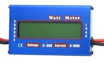
Got on line, decided as this "is just a test" to get a cheap knock-off of Doc Wattson. Plus what I plan to do I may blow it up. Reads volts, amps (1 way) & watts being drawn-4th window gives total of watt hours, peak watts, total amp hours, peak amps, 12v min. This one is rated 50 amps continuous/100 peak, non back lit (NOTE any and all of these meters are rated at constant half of advertised peak amps). There are some others rated higher amps, back lit etc. This is cheap-I mean cheap. Our inverter is a 400 watt solely to run TV or charge laptops. Most this might see is 10 amps but I believe less.. Which is why- really just guessing. I calc'd the numbers and came up 8.8 amps thru inverter using tv & sound bar. Hooking up ammeter to check between battery and inverter showed 3.3 amps? So either my calcs are off, the way I was running meter or no dvd in TVs player, so no sound being replicated (powered) or likely all of the above.
Again strictly out of curiosity, as we use the inverter to drive TV w/dvd, the soundbar 15v thru its converter, sat box when used 110v, recharging lap tops. Only thing this will result in is knowing actual numbers of accumulated use thru inverter. Only thing I could eliminate/ save would be inverter use for TV & I'm not cutting off tvs power converter to run direct 12v. I don't trust the fluctuating 12 in camper, Many people do though with out issue.
I'm pretty sure after a while and have a good handle on inverter use- it'll get turned off. However it occurred to me looking at how to wire and 'since I'm there'...a dedicated volt meter and amp meter inverter to monitor battery that's easily seen would be nice. Actually really nice. We use the solar panels meter now to monitor, not in the most convenient location, dark and have to wait for it to cycle thru its reading...so the project grows.
Ill add some links that I found useful. Many uses and ways to wire these.
nuff chatter
Mods to the meter
-
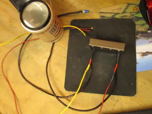
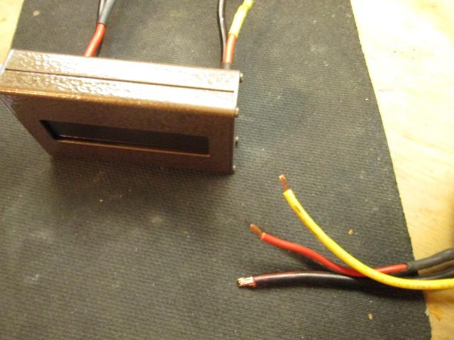
The watt meter case is about 3/12"x2"x3/4" thick. It is intended to be wired to and read thru negative lead between source (battery) and load (inverter etc). Alternately you can wire battery (negative) on load side and source could be solar etc to use&read charge versus discharge. The positive leads go thru meter but are only used as a thru point and to power the meter. The power wire is not measured. On camper no reason to run full current positive lead thru meter. Just connect a small wire to load side red wire (actually doesn't matter which red, they're soldered to same point inside) an run to a 12v source, its self use is very small. Cap other positive wire. I'm connecting to switched side of inverter on switch so meter is only on when inverter turned on. The ground or negative lead from inverter to battery I'm cutting and splicing in meter.
The wiring on meter comes out sides. I'm flush mounting meter and don't want to 'see' the wires folded back and going thru wall. Which was one of the things I looked at when ordering and decided on this one, the metal box is screwed together allowing for easy disassembly.
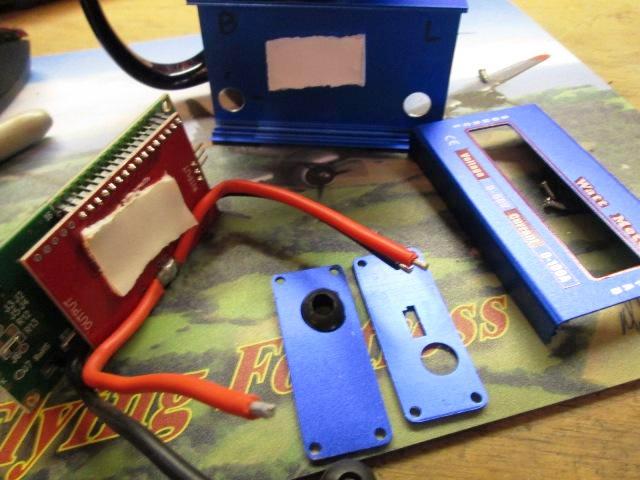
Taken apart, the meters board are only attached inside case with some double sided sticky tape..Using the ends as guide I roughly placed holes for wires to enter out rear. Load side hole needs to be pretty close to end for folding wire over as the rear board is close to that side.
You can see the positive leads above, again they only supply power for meter (minimal) so no need to run the main 12V postage lead thru meter. On the negative I was going to remove the 14ga wire and replace with 10ga and wire direct to inverter/battery. I'm still debating but I probably wont primarily due to getting larger wire out of case and the amp use this will see a non issue I think.
Well since it was apart-I couldn't resist the urge to paint the Bright blue case.

Was going to paint with some flat textured black, but had a bit of hammered brown left. Nice.
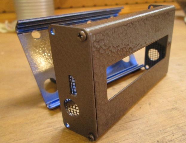
Also (and after painting) decided to drill a few of holes across the back for venting. Glued some nylon screen on exposed large abandoned wire holes.
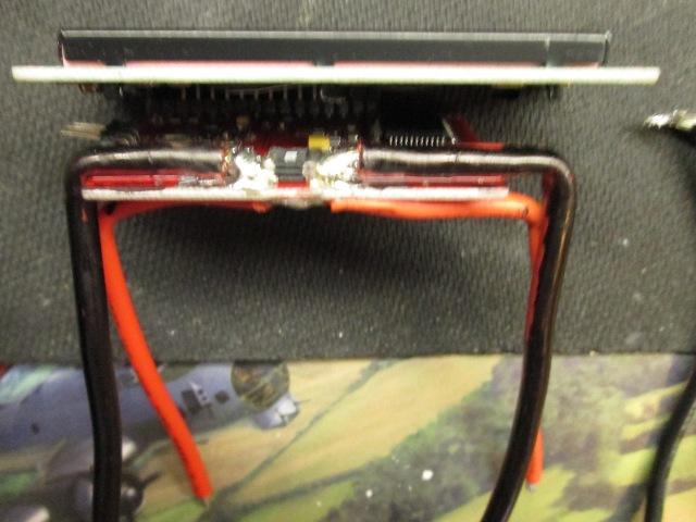
Nice fuzzy picture. Not sure how many times I went back and forth but since I had apart & after realizing the length of ground wire was getting extended removed & replaced the short 14 ga ground wire leads with 10ga that will reach inverter and battery ground. Didn't really want to be soldering on the board even though the reduction in wire size from 10 to 14 plus extra connections made sense replacing.
Removed lead from campers negative battery connection to inverter wire, soldered to the load side of meter. Cut a new piece to feed from meter to battery connection soldered to source side. A bit tight, just kinda fold back the top plate to get enough room. See the little stacked squares between the new leads, that's the onboard shunt-cute little sucker. Where most screw up is re soldering- as you can see there's already factory solder on the stacked shunt-chinese QC. But you don't want to add ANY solder to shunt, stay behind and on pad, messes up readings. I also super glued the wire sheaths to board as a bit of restraint. Unless your running huge amp loads no reason to replace the leads. I only did cause I was there...
Reassembled, tested and it still works! no change in readings. Figured at best 50/50 Id ruin. Soldered on a lead for the meter power. I was going to seal other unused red wire. Occurred to me that since this has no effect on meter it could continue on and be tapped, like for a light. So added a length of yellow wire, likely add a momentary switch and a small LED light, maybe, but its there if I want. If I add light Ill add like a .5 or smaller inline fuse before light as this source is from the inverters remote turn on switch. That's the plan-, if remote power cant supply both meter (and light) Ill run to another 12v source and switch meter and light power on/off with it. Meter auto on & off would be nice with inverter so Ill try first.
Powering meter with inverter remote switch-tapping power for light thru meter...both Bad ideas-updated below.
Just testing in shop,
All that's left is to mount and hook up. See what I've not accounted for. At some point I am adding switch, which I don't have on hand, to meter power feed, to be able to manually turn off. Its only 70ma I think (Note Doc Wattsons consumption is .007!) but sometimes... Actually a switch on ground leads bypassing meter wouldn't hurt in case there's an issue. Where to draw a line, I can easily access, after cutting wire from inverter it will reconnect to battery ground, but I could....ha but I've gotten enough entertainment for today.
Just FYI- I looked up how to guesstimate power consumption of inverter. It its idle load + load (watts � its efficiency number). Common is 85%/90%.
Ours is rated 3.6 watts at idle/no load, and 90% efficiency but used 85% to be more conservative. Also used 12.0 volts in formulas.
(consumption: Power (inverter idle watts) + load (watts divided by efficiency of inverter) = usage
FYI (convert amps to watts: Amps x Volts = Watts)
FYI (convert watts to amps: Watts � Volts = Amps)
So Ours
3.6 watts (inverter power) + 42.36 watts (TV load 36 watts � 0.85) = 45.95 watts
So that's 9.95 watts (0.83 amps) over actual demand using inverter to power tv.
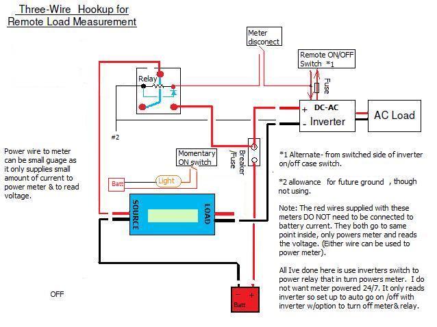
This is how I planned and wired
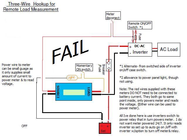
As explained below this didn't work...powering meter with inverter remote switch got low/fluctuating voltage reads, planned power tap for light-wrong to much pull thru inverter circuit--
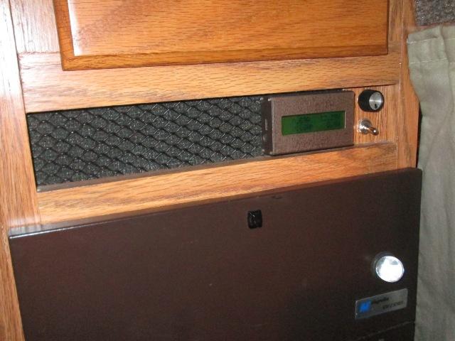
Installed
-
All that's left...ya
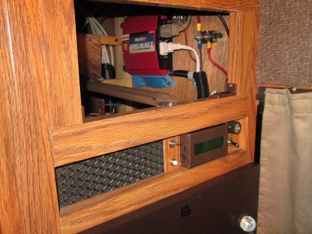
Well getting to the backside of inverter, reconnecting the ground wire to it took forever. Working thru a 5X10 drawer opening to access as our inverter is hard mounted on wall under kitchen counter. Anyway done. Meter is turned on with remote switch simultaneously with inverter. Kinda nice. Still will add a switch later to disable.
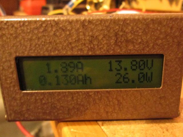
Everything was working-got a few numbers before packing it up for the night.
However I'm getting some kinda odd voltage readings. Tad low, minimal 12.2 verse 12.4 by multi meter and solar controller meter. Its also affected by load which I'm sure is also effecting the watt/amp readings. I think powering thru the remote switch feed there's is too much restriction and/or just too much before, not sure. I've had the inverter apart before, the power up switch is some micro traces on internal board. Sorta think this loop I tapped is restrictive on what it can deliver and being consumed. Just 'seems' new meter is somehow subtracting load from volts? Hows that work.
Puzzlen...
-
I had originally added the remote switch to existing inverter switch when I installed several years ago and has worked flawlessly. Wire takes off from power side of inverter switch, goes to fuse, 3' of wire to remote switch that has pilot light, back to existing switch. Point being it was easy to tap the power going back to inverter that's controlled by remote switch, thinking I could have a auto on for the new meter. But the readings are off...
Well pondering this as I write... Never thought the inverter switch wasn't actual 12v hot....hmmm, more I think about it its part of the standby circuit... Maybe dunno. I'm thinking the power supplied for the on switch isn't true line power but something supplied by inverter internals.
Ding-Ding. well this was puzzling but I hadn't checked the remote switch voltage with multi meter- if its regulated power thru inverter to feed switch that in turn turns on inverter I could see this not being line power. Would explain the variable volts with load. Which kinda makes sense because its feeding what ever circuit turns on inverter....
I had good numbers in shop. I'm checking the remote power tomorrow but I bet a dime against a dollar that inverter switch power is throttled, there is full power at the thermal breaker that supplies inverter. If what I'm concluding is true, will run the new meters power wire to another good source (not part of inverter). If the numbers are more in line with other meter volts then I guess Ill add the switch sooner than later and nix the auto on with inverter. Not sure where I'll put switch...I almost added a switch to case when in shop-just incase-oh well, its not coming back out now. Actually pretty sure in any case that's what I'm doing. Wanted a switch anyway to manually disable, but now it will also turn on. Its seeming like pulling or using the inverter switch isn't a good idea, wasn't designed for load. I could do something with relay powered by inverter output to make auto on but this is getting silly. More than likely after a few months this wont be used once I've collected and seen numbers from various items.
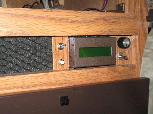
Well anxious to get back out there but it'll wait..meantime pictures of meter installed. Get some better daylight pictures tomorrow.
Kinda nice-well better than the brilliant metallic blue. Kinda not noticeable.
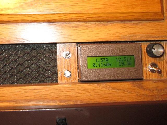
NOTE-rheostat knob and switch on the right are not part of meter. They were added previously to inverter, spliced inline on power wire for its fan. Our 400 watt inverters fan is either full on or off. Quite loud. 3 way switch sends full power to fan or thru rheostat to slow down like when watching TV.
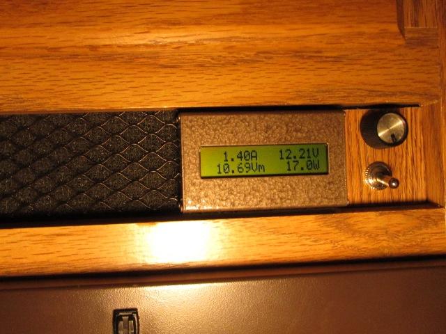
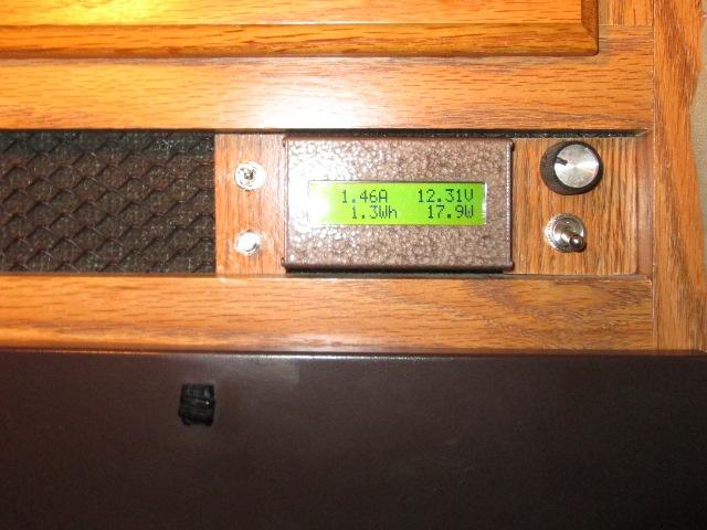
Interesting. Showed about 0.75-.85 watts, just meter & inverter on with all cords unplugged. ~17 watts with extension cord plugged in which is TV, sat box and sound bar in standby mode. What this will give us are real numbers, accumulate total watts for say watching a movie for x hours or charging laptops for x hours. Verses just seeing volts drop or guesstimateing by what solar is putting back. Anyway entertaining for a while..
Rewiring...
-
Wow...Having concluded I shouldn't draw additional power thru inverters remote switch, (doesn't show line voltage-likely burn the inverters board trace) and run 12v direct power for meter with a manual on/off switch I started taking apart. However I decided I really wanted this to auto come on and go off with the inverter.
Giving it some more thought I figured if used a small relay triggered by the remote switch I could still have auto on/off but actual meter power from line voltage (not thru inverters internal switch circuit). Also If, though pretty much decided not, if I add panel light powered by remote circuit just asking for failure. So pulled and rewired.
Finished rewiring, powered up but the inverters fan not coming on, so in the middle of pulling inverter... uuuuhhhh. Cant leave well enough alone. But It is (was) working. Meter showed more in line with line voltage, though about 0.2 volts low, However these cheap meters have no adjust pots. Anyway we've auto on/off meter with manual disable switch. Made a small panel to hold meter off switch and new panel light switch (independent of meter & inverter).
Liking it, but as mentioned, while in there fiddling with the wires, broke lead to inverter fan right at the back of case. Cant access with inverter in cabinet so out it all comes. In the meantime this is what we did...
The (new) plan..
Tap inverter remote switch return to energize relay (30ma) with a switch to manual turn off. 12v source from thermal breaker that supplies inverter, when relay energized supplies line 12v to watt meter. Also, though left ground for future use, panel light power is separate.
Just on
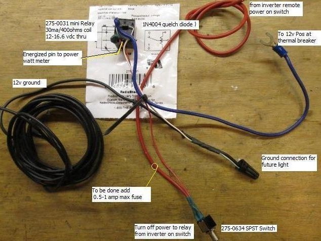
And the execution, hmm well prewired. Once inside I can tidy a bit. Added a 1 amp fuse on trigger wire before it taps the remote wire. If there's a short will still leave inverter switch operative. Not sure where I'm getting ground so left long, likely at back of inverter- I think that would show or add relay to inverter use as meter measures the ground. But Ill check if no difference in readings could add relay ground direct battery, just easier. Ended up running to inverter (thru meter).
Trimmed a small piece of paneling to hold meter switch and new momentary switch for led strip light. When I picked up the relay and switch I ended up at car parts store looking for lights. Picked up license plate light but also an led flex strip light. The packaging has a small battery pack and a nice 'lil push button momentary switch. Intended just to 'see' & sell the lights its a perfect stand alone unit for camper. Not shown & wont do until meter is finished but the light Ill add a length of 1x1 above recess panel. Stick the leds to bottom and they will shine down on meter(s). Eventually I'm adding a volt and amp analog meters here to monitor batteries. I may also make a full face black plate for this whole mess looks a bit 70s. Or just paint the panel with the brown hammered tone.
Got the inverter fan wires resolderd, reinstall it tomorrow and button up this silly project.
Re re-wired/installed...
-
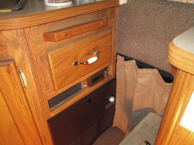
Remounted the inverter-jeesh.. rewired. Whose brainiac idea was this to bury it back inside drawer opening?..Oh me.Did give me the opportunity to clean up some wiring while in there.
Nice, wiring was a disaster. Though when drawer in there you don't see. I do appreciate not seeing rats nest but could have lived without redoing. I had added a 1amp fuse to meter switch-but the remote is also 1amp, being closer to source need to up it or lower the meter feed. Ground I ended running relay ground inverter so it also goes thru meter. Left ground stubbed for future use but the light I'm using is an independent self contained unit with its own battery.
Again-rheostat knob and switch on the right are not part of meter. They were added previously to inverter, spliced inline on power wire for its fan. Our 400 watt inverters fan is either full on or off. Quite loud. 3 way switch sends full power to fan or thru rheostat to slow down like when watching TV.
Top left switch turns on/off meter ,push button bottom left is for small battery self powered light behind grill, never mounted. .
. Kinda odd watching meter-It varies. With inverter on, TV, SAT box and sound bar in stand by- watts fluctuates ~17-19 watts. Worth the effort as the volts are reading closer to line, otherwise amp/watts reading virtually same. The volt reading is on the load side, its about 0.2v less than line which is measuring 12.5v. Yesterday line at 12.6, meter was showing 12.2 and varied with load. So a bit of correction moving power from inverters switch circuit and voltage doesn't fluctuate with load. Or not using relay just connecting to inverters 12v source would have worked. Didn't do any other testing. Leaning toward the meter is just off about 0.2v. As long as its consistent to get relative readings works for me, get what you pay for. As mentioned, If I were to add one of these, say to monitor solar or batteries, Id spring for Doc Wattson.
Preliminary readings though are in line with the what I showed with multi meter. And way less than calculated use. TV on, DVD playing with sound bar on at usual volume showed total of 3.65 amps, 34-46 watts. What surprised me is ON for any unit is only a few watts higher than standby draw, or I guess more accurately how high stand by power is, though we don't leave inverter on only using. What surprised me more are the totals when turning multiple items on. Calculations adding up I should see closer to 9amps-but both multi meter and new watt meter show at max peak of 4amps with everything on. 'Cept the Sat box, didn't register increase thru meter when turned on, I'm assuming because dish wasn't hooked up it was in setup mode? I expect that to show a significant draw. Anxious to see that , and what the laptops draw when charging.
Other than breaking stuff, rewiring twice, kinda fun project. Again strictly to satisfy my curiosity on actual usage of different items on the inverter. Should be entertaining for a while. The light, though wired in, I need to mount-haven't quite figured that out yet. Meant to get picture of the light I'm adding but its inside behind drawer- forgot. Another day, another project..
Bottom line so far, all this exercise did was validate the use of our inverter to power TV. The calculated added overhead is 3.65 watts (Inverter) + 10-15% of TV load, but the actual numbers are less. Since we need the inverter to power sound bar or Satellite box the added requirement converting the DC to AC to use TVs inline converter (even at higher cal'd numbers) draw is just minimal. If we had no charge source-1 battery, only used TV, cutting off its converter would save a bit and might make sense. Its so small I cant justify the perceived risk (and personal luck) with campers varying voltage running direct. We only run a max of 3 hours? Save more by converting 1 light bulb to LED. So I am unclear as to why folks do.. I assume, as it does seem silly converting DC to AC then back to DC, there is some perceived huge savings NOT doing so.
The preliminary meter readings WILL save on power use, though inadvertently. We have 2 receptacles that are hardwired & plugged into inverter. 1 at dinette for laptops etc and the other at TV. The one at TV has a 3 way to plug in the various components. Only time its unplugged is to move to shore power receptacle when we have it. Point is when the inverter is turned on to charge laptops etc, the TV etc are also receiving power. Never occurred to me the stand-by power being used. Likely as much, maybe more, than laptops are using- too funny.
Lastly some links. One of course is to the original Doc Wattson meter. This would be the one I would use if I were adding to my system; IE solar output or to monitor batteries. The amount of information on site in my opinion worth the extra cost of the original meter. Not to mention quality
UPDATE 08/2020 Issue with website rc-electronics-usa. -unable to find items for sale/discontinued so removed active link. I don't know if business closed or what, found some links selling under Tenergy brand but also now listed as unavailable? Unfortunate, awesome product and wealth of information. With so many clones out there the original gone...
For camper use their "Doc Watson R102" model is a better choice for campers.
Sure hope no one ends up here looking for real information. Actual installation is pretty straight forward using 3 wire hook up-visit rc-electronics. They have several diagrams, and other useful information.
Back to Ourelkhorn Camper Modifications page