Amp Power Step (electric running boards) on 2001 F250 standard cab
Better title after installed would be "Adapting a 4 door power step kit to use on a 2 door standard cab"3 years later...a rousing thumbs up for the Amp research steps- both hands...
Installing Amp Research Power Steps on our F250 standard cab truck. Last couple of years I've been utilizing our small folding step, setting up when is Margaret climbing in and out of truck. The almost 2 1/2' hike just tweaks her. I decided to go for the electric steps so its not obvious she needs them, at least that's all I can surmise as she will often jump out before I can get around and suffers for it. Or I forget.
I dislike most running boards on newer trucks-they just look stuck on. Some can be as much a hazard as useful. The electric folding steps when not deployed retracts up and are all but unseen. When deployed they also extend further out and lower than bolt on steps making them much more suited for purpose. Biggest draw back is the cost , at least twice what fixed bolt ons cost, however twice as useful. When I mentioned considering the steps, her eyes lit up, when I mentioned my reluctance because of cost she said order them.
So the projects a go. I spent several days looking at different installs/videos etc. Trying to get a handle what might be involved. I did not find one single install on a standard cab. The kits are listed as fitting standard. extended or 4 door cabs, so install should be the same. The main thing I did pre determine is I want to be able to manually disable steps. Couple of reasons, one being the intermittent Ford door ajar switch sticking. I don't want to be fiddling with steps on the road or trying to free door switch (or replacing). Simple off switch would avoid that. Second, my opinion, is auto anything needs a way to easily defeat.
Preliminary; install switches while waiting for steps to arrive
Basically only covering what might be unique to installing on standard cab and my variations. (I guess I could make a video of them extending and retracting when finished, like that's really helpful?) But there are some good install videos out there.
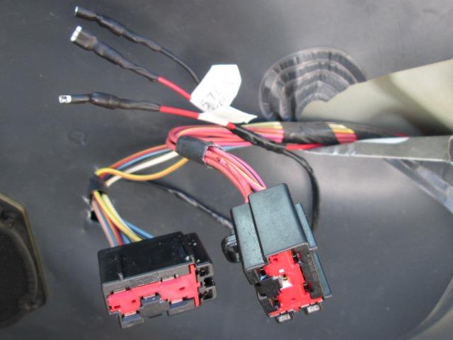
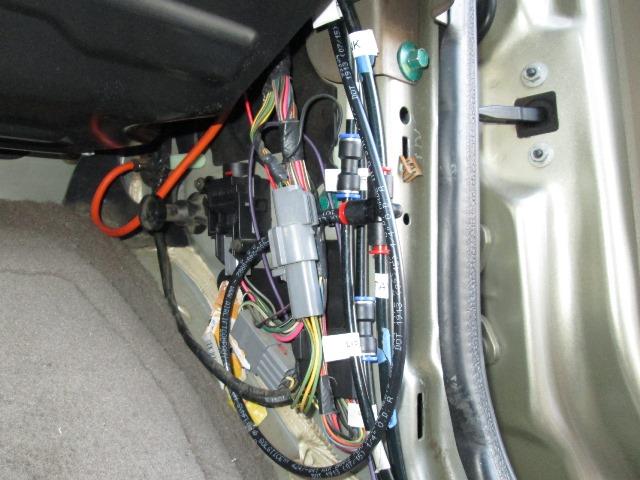
Waiting on steps to arrive I decided I could install the switches before hand. The power steps use the door ajar signal to trigger the motors. Its a ground signal. So a simple on/off switch on the wire that will lead from door ajar switch to the motors trigger wires would cause them to retract if issue with door ajar (or I just don't want steps to deploy). Turning the switch back on would allow them to deploy.
I realized by manually grounding I could deploy steps without opening door. Not really needed as this can be done by placing foot on the when deployed and closing door they will stay out. But since I'm adding switch to manually disable using a SPDT I could manually deploy.
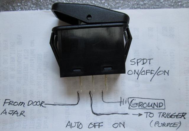
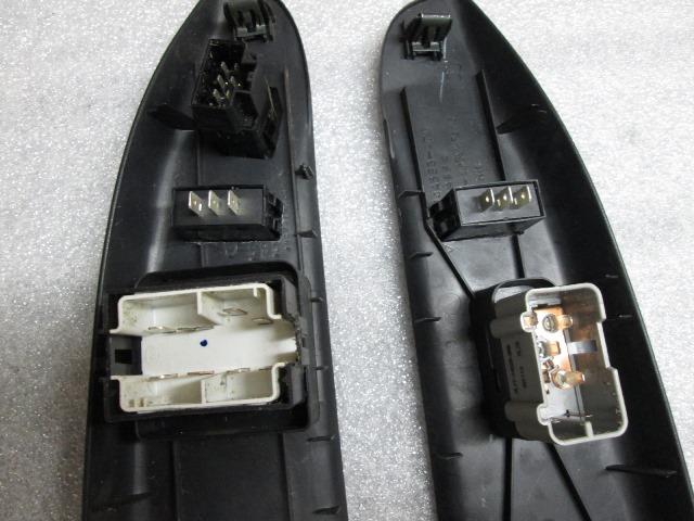
Auto, off or manually deployed. Easy peezy. As I have to get into door to add wire tapping the door ajar switch decided switch would easiest to wire if it were on door. Run wire from door ajar to switch. Run a ground wire from switch to mirror light ground wire. Run the wire that continues to step trigger wire. Switch allows door ajar ground signal to continue to motor trigger (auto) or not (off). Manually on just grounds motor trigger wire. Hardest part was finding a SPDT switch that would look ok in truck. That will determine where they go.
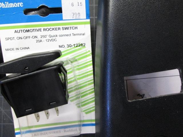
Luckily Radio Shak happened to have 2 SPDT on/off/on switches pretty close to what's already on the trucks door switch panels. So that's where they are going. I hadn't planned on cutting up truck but this will be convenient once done. Probably closer matching switches could be found, certainly cheaper but this is driving to town and bringing something home today..These folks looking on line do make similar sealed switches.
Cutting the panels not difficult but the switches have a very small bezel over hole size so its gotta be pretty dang close. Laid masking tape down drew out the rectangle, drilled corner holes then scored with razor knife to holes. Dremeled the straight cuts, fished/connected the cuts and holes with hacksaw blade and xact-o knife. Intentionally cut on the small side, used mini files to clean and open up until switches just fit. Worst case always buy more door panels
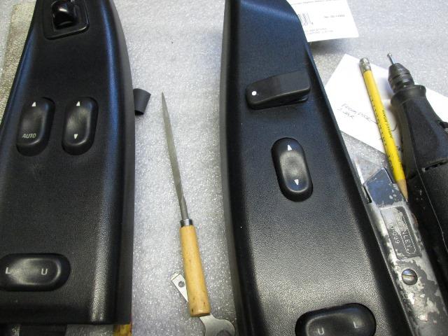
Got the passenger side cut. I did have to trim the door panel for switch
There's a web on passenger side that isn't on driver side. I could have moved switch but wanted both sides to match.
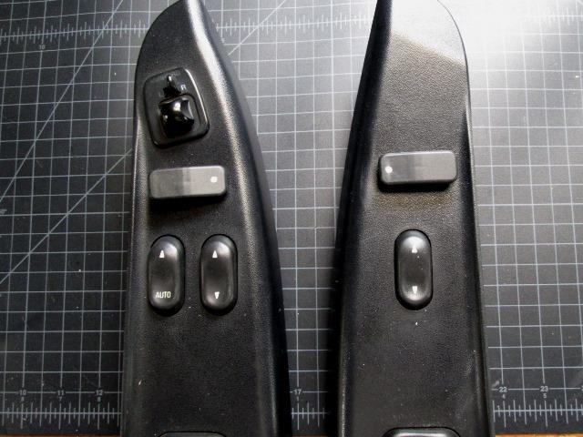
Mostly on drivers side there is only one other open space and it may get used to install heated mirror switch if I ever hook up. Got the drivers side cut. Used ball on dremel to cut small dimple in switches, filled with paint. "Dot Down" is auto. Both switches auto is inboard, I assume normal position. This will help from inadvertently hitting and changing function but less visible under switch lever.
Once ready its just plug in.
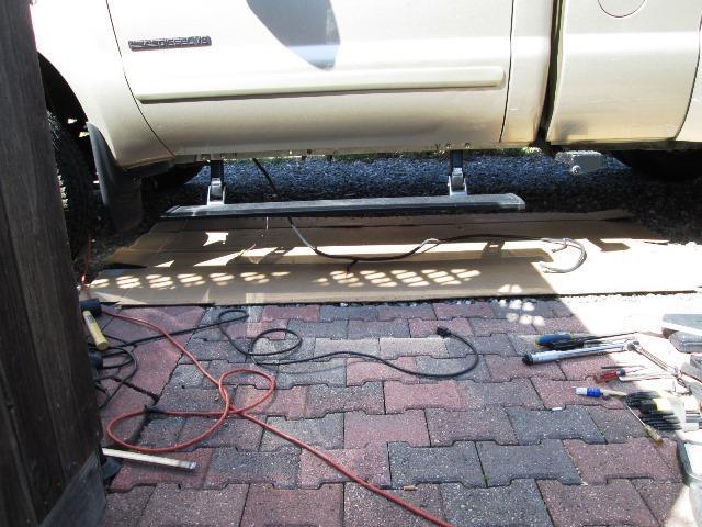
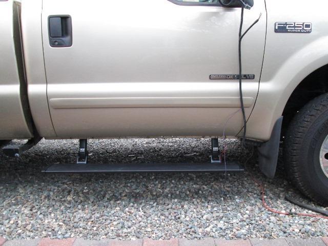
STEPS arrived! Our install
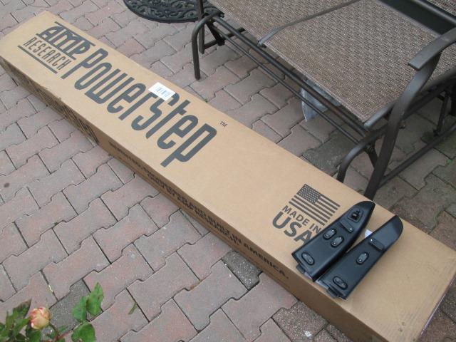
No sooner finished that the 'lil brown truck stopped!
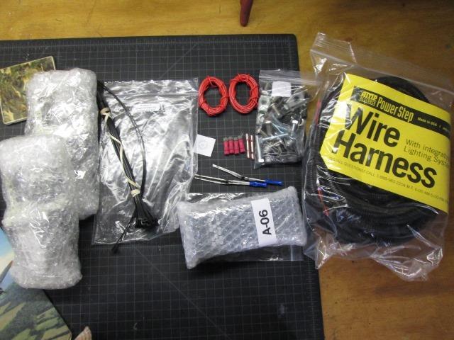
Parts is parts. Over all quality of the Amp Research components is nice. Pretty stoked.
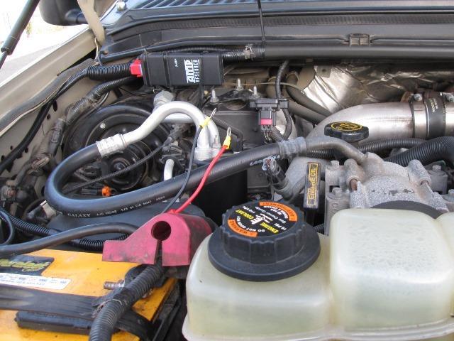
As mentioned not rehashing the general install but departures. In engine bay and locating the control box. I don't have quite the clear space on fender well shown on instructions, plus would put a lot of excess wire between it and battery so moved to rear instead. Still some details to clean up, filing the eyelets so they fit my battery clamps? also covering with shrink tube. On to installing brackets.
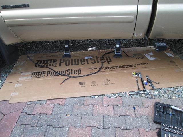
And Stopped. Didn't get far after mounting the brackets, routing the wires pretty much standard but this is where I'm at . Couple of issues. The wire harness, as this kit will also do a 4 door, is like miles too long. Easy enough, I'm pulling the loom, and cutting out several feet of wire placing motor plug and light outlets where they need to be. Minor. Only plus about this kit set up for 4 door is I have extra pair of lights, Ill double on the step. But second issue if it is one I'm unsure about. On standard cab the 2 brackets are pretty close together, 23". It also puts about 16"+ in front of front bracket. Seams most of the weight is going to be on front idler bracket, easily counter levered the front. May not be problem, but it sure looks funny, actually looks stupid.
My conclusion is, as diagram of placement is different than what's under my truck, is that non 2door trucks are configured different. Though curious, next time I'm near a 4 door I'm looking underneath. As there is no mention of needing to drill a hole, or shimming because the mounting surface is not flat, also existing square hole that's shown to slide BOTH u-nuts will not work for forward hole, its narrower and forward u-nut must be slide in from the oval slot. So one would assume, as I did, you would use the second set of holes that allow for direct "bolt-on". However that puts the idler arm all but in the middle of door? My assumption is that the distance on a 2 door to the second set of holes is greater than on 4 doors. I find it hard to believe that's what is intended, Unless the manufacture has never tried and 'assumed' std. cabs same. All of the pictures I've seen indeed use second set of holes but the brackets appear farther forward.
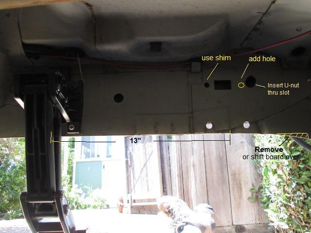
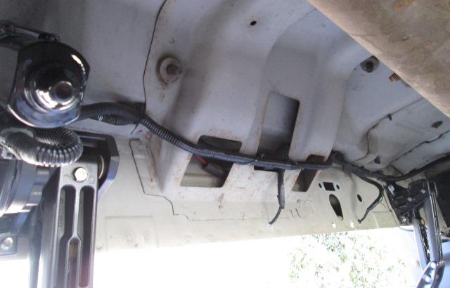
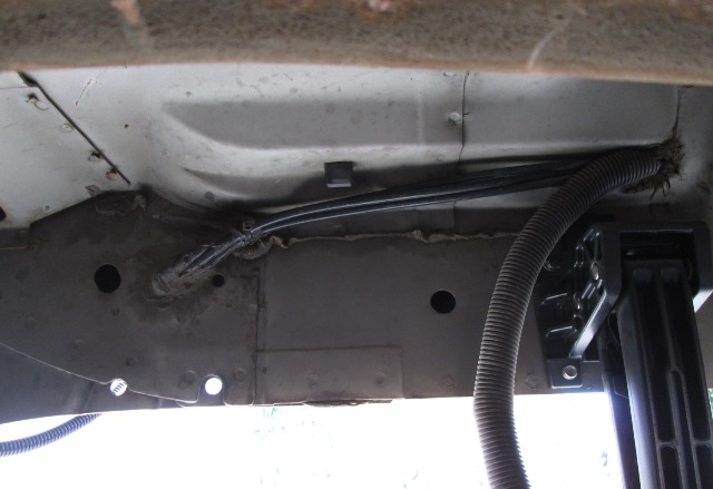
This is looking under drivers side. There are holes toward the front that could be used moving arm forward 13". Would require shimming as its not flat and drilling one hole. This is what I would use IF not for the passengers side, the front holes was utilized to run 3 air lines. Still pondering. I could cut the air lines and move-just seems like a lot of work. I could move adding holes about 8" forward where its still flat. But that's lot of holes....I just cant continue-trying to talk myself into just installing per instruction.
- Modification/install drivers side
Well the clincher was laying out light placement in order to rework the harness. Instructions say 27" from front of door but stepping up I consistently hit about 16-18", right where bracket is and a bit forward. Second light Ill put about 27". But I still don't like the brackets so close to each other and the really large overhang, more I look at the more wrong it looks. Decided to look and see if moving forward, step would still function, maybe there's a reason other than drilling a hole? Need to prep board so I can mount to verify its not going to bind brackets or something.
Cut the running board 50" instead of recommended 48" just for appearance. Always shorten. Used sawzall. Then I drilled the needed 4th hole. I thought I would need to enlarge the square hole, front one is shorter but the U-nut slipped in from oval slot side. Used a 1/2" flat washer under rearward top bolt. Loosely assembled. Placed the board on brackets and snugged up a bolt at each bracket then tightened up front idler bracket. Looks like it will work?
Plugged in the motor loosely (easily unplug to stop), put the fuse in, I heard the step- yanked the fuse. Didn't realize when powering up even though ground not hooked up step tries to return- duh like its supposed too. So unplug the motor, put the fuse in. Plugged the motor back, it stopped because front corner is hitting body lip, but just barley. Grab front of board and pulled down, manually grounded the purple trigger wire, step cleared and fully retracted. Remove ground while still holding board edge, step fully deployed! Got out the grinder and took off about 3/16". Filed it smooth, brushed on a bit of zinc primer. If board was shorter and moved rear ward It would clear without massaging. Only reason I can think, using second set of holes on a standard cab is the need to drill a hole and the uneven surface. On an extended or 4 door cab placement wouldn't look wrong. Anyway plugged it back in and played with the step for a while. Works awesome.
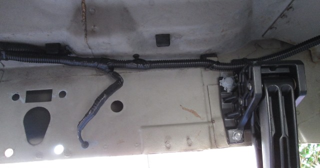
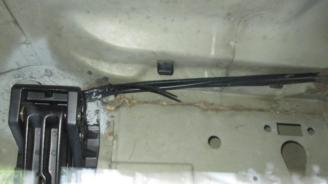
After wiring was done but showing relocated front idler bracket. Blobbed more zinc on bolts, once finished I'm replacing all the upper hex bolts with stainless. Wished Id got some before installing.
Front bracket relocated forward. Now were happy. Correct in my opinion, least for a standard cab. Equally spaced, should spread loads, less likely to bind. The more I get into this, especially starting the wiring- I've concluded this really isn't set up for 2 door. Not sure why more specific kit isn't offered. At minimum wiring diagram for 99-01 2 door would be nice-I'm second guessing on the diodes, all other years diagrams are included. Seems just the extra length of 80" boards, wiring excess, loom and second pair of lights etc would offset cost of separate kit. Who knows. Placed and drill holes for the lights to start cutting harness. Painted holes.
I silicone caulked all edges of the lights- clean truck with alcohol and mounted lights with pigtails inserted thru grommets. Now to lay out harness. What I did after removing all the tape, pulled light wires out of loom. Looking at pics above, the first light wire pair is 'almost' at rearward light, though a bit long. Instead of cutting and re splicing it all, I just folded the first light pair wires in loom back about 6" so it will exit loom at rearward light. The second pair of light wires (that would normally go to rear door) I folded back and exited loom at forward lights. From the light wires going to front, even doubled back I still cut off about 3'. Re-taped the short 6" loom sections to main loom. The light wires extend about 4" so when I solder to LED wires, the connection will be inside the loom. I didn't use supplied butt connectors.
I had about 5' extra on the motor lead. I was going to coil up but that looked really stupid. Cut plug off with 10" of wire then cut off 4' from main harness. Soldered the plugs leads together. Shrink tube, and taped all the loom joints, starting at front zip tying to truck. Oh....
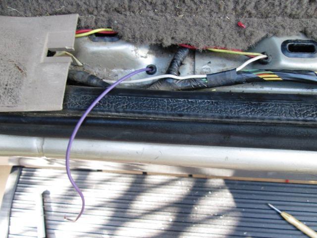
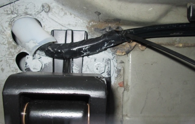
Almost didn't mention. When re looming I looked at where purple trigger wire should exit. Instructions say to run the purple trigger wire over to middle of footwell, pierce the grommet, run wire up thru then run back over floor to door sill. Why? Loom is directly under sill? Drilled 9/32" hole. Run trigger wire straight up into sill.
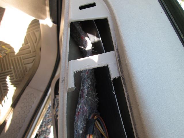
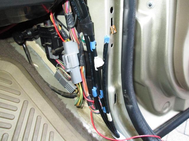
Drivers side mounted and wired. All that's left is pull door panel and pull & connect wires to switch. Though I've snaked wires thru door boot when I added lighted mirrors. Not looking forward to that. A length of plastic tube is supplied that in pushed thru the boot, slip wire thru then pull tube. Sounds good, but on our truck on the kick panel where boot exits inside, opening is covered by is a wire loom cover and ebrake. Its a bear. Tomorrow- Then its doing the passenger side. Should go a bit quicker-not counting rerouting my air lines. withstanding
I did check out the lights tonight, kinda purplish blue but fairly bright. Nice, if you into the pimpy kind of thing.. The extra lights made shortening the loom worthwhile, though I wished I had tested before hand. I would have and may later get some white or amber LEDS to swap out.
Day 2: Button up drivers side wiring. Fishing tube work well inserting as far getting thru boot, still fought getting the wire thru under dash. But got it-if someone else reads this, if nothing else, IF/when you finally snake wire thru door boot-pull a doubled piece of string thru with the wire. Last time I was in here I didn't because 'I would never need to do again'. Here I am, fighting it again. This time now that I have wire thru I'm using to pull doubled string thru, tie off the wire (and probably an extra string) with one of the strings and pull it back inside. That leave 2 pull string inside in case I never get back here.
Anyway wires run, ran wire from door ajar to one side of switch. The other side is direct ground. Center position runs to trigger wire in door sill. I ended up soldering all the connections, crimp on connectors at the switch. Checked it out and it works as it should. Open door step deploys. close the door step retracts. Move switch to manual step deploys, turn to off step retracts, whether deployed manually or auto with door. In off position step doesn't extend with door open. I just hope when I get the passenger side wired it still works- due to lack of instructions for an '01 2 door. Really don't know if the diodes are required. We'll find out.
- Passenger side modification/install
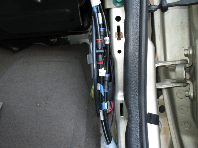
Opened up passenger door ran its wires tapping the door ajar, taping direct ground and pulled the trigger wire down to door sill. Reassembled door, plugged in the new switch. Haven't tested yet. This side took 20 minuets verse 2 hours fighting the other side. If it were not for the air line issue another hour this would be done.
I'll probably spend a lot of effort trying figure where to cut lines and where or how to re-route. Once they are out of the way should be couple of hours to button up steps and reconnect air lines. I really don't want to cut airlines. Easy enough but, still looking at just moving brackets over to flat area before front set of holes. Just need to do it.
And did it...
Nice fuzzy picture. But arm moved forward. Decided to cut the air lines inside cab. Several reasons. Mostly once I cut new hole & reroute lines I can re-secure them underneath. Under dash is where I have excess slack, recoupleing will be easier. Also easier if any leaks to readdress. Couple lines back together later.
Staggered cut the lines so they'll only go back together one way, Opps forget to bleed tank- well now I know which is pressure line.
Pulled the lines down out of the way. Bored an 1 1/2" hole above & to left where they previously were and where idler bracket will set. Drilled 4th hole for idler. Used a hair dryer to slightly warm tubes and fished back into cab. For now cut strip of poly to make a sleeve to protect lines. But airlines that I was stressing over done, well out of the way. So I can mount the idler forward.
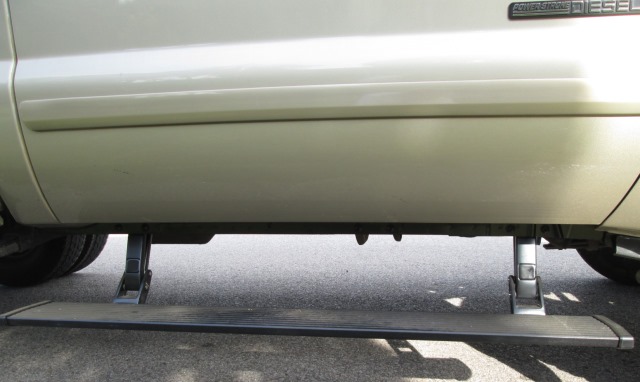
Loosely mounted idler, plugged in motor. Using trigger wire to manually move arm, stopping by pulling plug. Cut board to length and Loosely mounted it to arms. The jiggling everything and tightening little by little till snug, checked full cycle of step. Works! Ran torque wrench to finalize and checked again. Passenger side clears the body lip where it tapers down in front but its close. Went ahead and trimmed it.
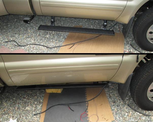
Marked and drilled holes for lights and hole into sill for trigger wire. Clean & and primed them. So all that's left is rework harness, connect trigger wire in sill and the lights, steps done. Tidy it up. The middle set of holes seems to be really obvious now, Ill get some more bolts to fill. The very ugly spot welded seam below door is even more noticeable now when step retracted. Ill mask it off and paint black. Just realized no pics of steps retracted-huh.
It also occurred to me since lines are cut inside I can use tee to re couple pressure line and add the air tank pressure gauge I bought years ago. Cool! But another project.
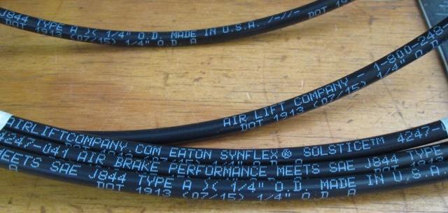
Shown at top is the way too long harness. Bottom is just right, for a 2 door... After removing all the tape on loom pull out wire. Starting at front place wire back in, set purple trigger to exit loom. As noted, I DID NOT run it over to foot well-pierce the grommet then run wire back to sill. Drill a hole (same bit as for lights) to enter directly into sill.
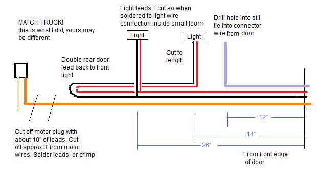
Just a simple diagram of 'made to fit' harness. Again wire intended to feed rear door lights on a four door are folded back to feed my forward mounted lights. Cut Motor plug off with 10" length of wire, 3' of motor lead cut out (3'-6" on driver side), then solder the plug back. Re loom and tape up harness. Hooking up lights cut 30" from rear leads.
Connecting trigger wire, if you intend to use grommet in floor check the length of purple wire BEFORE piercing. Mine would not have reached over and back and butt connection would have been under carper. Drilling up into sill I made connection behind the kick panel, cutting off several feet of the red connecting wire.
Again no mention with what to do with all the extra wire on a 2 door. IF you drill sill for purple wire closer to door hinge side, you could pull harness back toward engine. Limiting would be first light wire. Stuff excess loom behind wheel well out of the way-still might end up with couple of feet to be coiled at motor end. I didn't want a coil under truck so I cut.
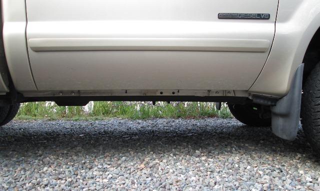
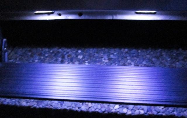
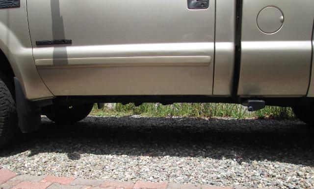
Oh picture of the step retracted. Camera is at bottom of sill height. Pretty cool. Really happy with the steps- not so much with the manufactures representation of them fitting, lack of wiring instructions for the 99-01 years and the placement on standard cab for the front arms. Someone should tell them ITS A DIFFERENT TRUCK!. I'm really curious if anyone else has installed on a standard cab and the results.
If not for the 'preference' of bracket placement, air line issue I needed to address and the wanted switched control with a harness that actually fit- this really would be a short day project. Let alone having to second guess the wiring for a non remote keyed standard cab. But again this kit truly isn't designed as a 'bolt on' for a two door. Its designed for a four door. But all the parts are there. Unless you bundle several feet of extra wire, can live with the odd front bracket placement and don't want switches, ya I guess its a few hours project. Pretty happy with results-just wonder what a normal person would do.
Course there are not that many standard cab Fords out there, few of those installing power running boards. Just puzzles me they can sell these as a 'bolt-on' for a 2door, maybe not to the extent I went but some tweaking needed.
Would I recommend this kit? Most definitely-I didn't have to go to the store once. Quality of component top notch, American made. I actually ended up restocking parts bin with several feet of mics. wire, split loom, nice shrink butt connectors, some power taps. Not to mention several feet of extruded board. Most importantly, Margaret can step into truck with ease.
Got some matching round head bolts to fill the unused center holes in seam. And bottom spot welded raw seam painted black, not that you can see it. Oh, that was the point...
Also blacked out the stuck on manufacturer logos, Why would anyone want to see that 4 times on their truck?
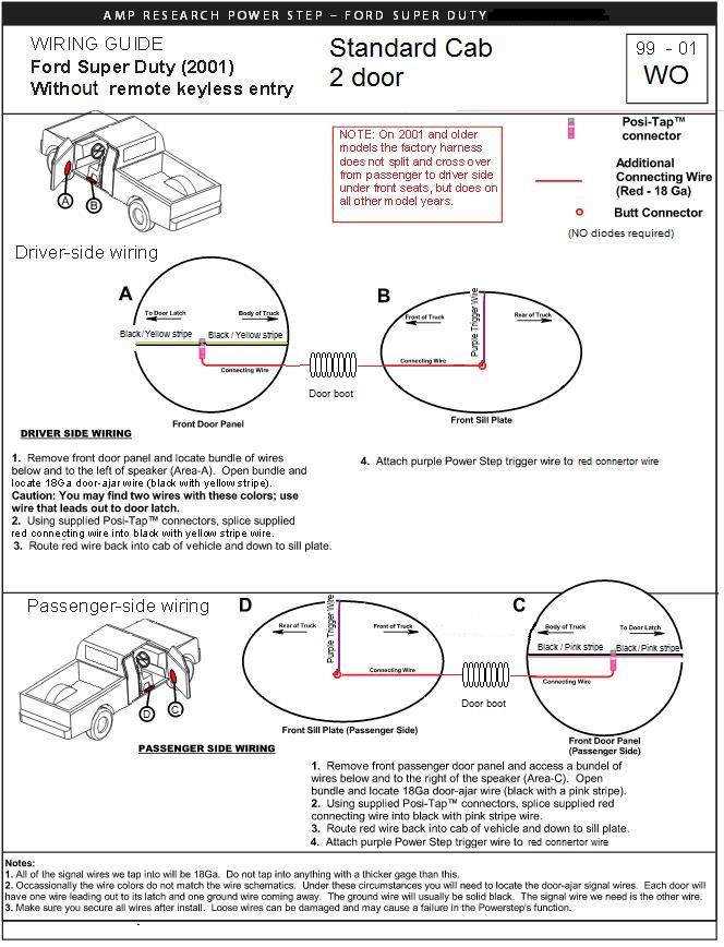
Wiring Instructions that were NOT included, (click for larger printable picture, will open in separate window). A simple statement stating that 99-01 2 door truck without remote key, the trigger wires are connected directly to door ajar grounds would have been nice instead of me second guessing....I guess they assume if no unique instructions its obvious? Anyway FYI
The obligatory video... Another silly useless video, no information, 1:08 minuets
Just watching step go in and out...
Simple steps but Margaret is smiling- worth the effort and cost.
"Custom' mounted, switched to use automatically with opening & closing of doors, allows manually turning off either door step or manually deploying, regardless of door position. On the Super Duties, at minimum I would add some easy way to disable steps, on/off switch somewhere, due to the door ajar switches prone to sticking. Course you could just pull power fuse. But with switch you can still use steps with a failed door ajar switch.
- AIR LINES RECONNECTED
Anyway parts finally arrived.
I had ordered an 18' length of Firestone- I received a 20' which was shipped directly from and is marked AirLift company? So with fittings on hand removed all the scabbed temp stuff.
Coupled the air bag lines back together re cutting all the tube. Routed about 6' of new tube (lots of excess) over to drivers side under dash. Not sure where gage is going so it'll hang for a while.
Tidy it up and labeled all the lines. Cant tell you how much I hate it when truck is in disarray.
For the tank drain, as I usually have to replace every couple of years, I added a tee with the new petcock on side. To the bottom leg of tee I added a plug. Hopefully petcock will see less debris.
Lastly was finding a place for the gage. Couple of places to mount in dash that would look like it belonged but not so convenient for looking at it. I have a quick connect behind passenger side to utilize air, like for scooter tires, blowing dust out of air cleaner etc. Which is really why I wanted gage so I'm not completely draining tank- shorter cycling of pump. But where I really wanted to mount gage, to left of steering wheel, I couldn't see it from passenger side. Just cant decide- function over form, appearance over practicality...
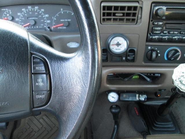
Seriously after 2 days I gave up. Made a small bracket and mounted gage beside brake controller. I can always move it. Perfect as far as sight from behind wheel or passenger side, either standing outside of door or seat...something for Margaret to monitor:). Does look a bit-well...But got my tank gage.
Found another use for steps. They are at a perfect height deployed for setting or kneeling on while working on stuff.
Back to our F250 truck page
Back to Ourelkhorn Camper Modifications page