Replacing the Magnetek 6345 charger/converter with a Progressive Dynamics PD4645

Our original Magnetek 6345 converter/charger worked but we usually aren't hooked to power that long. Its main bad point is its a continuous charger, and can boil the battery water out after extended run time. That type of charging just isn't great for long term battery life. Our solar on the other hand, which is working continuously does a good job of maintaining the batteries with its 3 stage charge controller.
Our converter, when we have access to power, the fan was getting really loud and ran continuously. Plus the last trip out-plugged in for 4 days, the water in the batteries had dropped quite a bit. As far as battery maintenance, this will only be a benefit when on shore power for us. But I figured it was time to replace and upgrade. Then a discussion on RV.net thread got me motivated. Not having to worry bout checking the water when plugged in for extended stays or listening to the fan roar. We bought a Progressive Dynamics PD 4645, 45amp replacement converter. Its basically a 4 stage charger, that replaces the existing internals of your converter (uses org cabinet and 110v breaker panel). The new converter also comes with a new 12v fuse circuit panel, which has LEDs to show blown fuses, and an led to show the charge mode its in-fun stuff. Has variable load controlled fans (2!).
You can get a lot more info on the features/benefits at the Progressive Dynamics mfg. web site or at the Best Converter site which is where we got ours.

Below is page from instruction book that came with new converter. Its really that simple. Disconnect all power sources from camper (110 & 12v). Remove wires as shown, slide out old converter. Replace 12v fuse panel, reattach wires, slide in new converter reattach wires. Probably took me 2 hours and that was modifying my door. I cut a hole in door so I could see the led charge mode light with out having to open it.- We have a digital meter on solar controller that shows that actual voltages in batteries, Just added for the heck of it.

Ill add a few photos I took referring back to instructions.


PD-Logo
Reference only:copied from the PD4600 series instruction book-page 2 (our converter)-you can access full pdf instructions on sites listed above. For installations use manual that comes with your new converter
    Replacement instructions for

    ParallaxMagnetek Models: 6336, 6345, 6355, 7345, 7355

    Removal;
    1. Disconnect all power sources as outlined on page (1) of this manual.
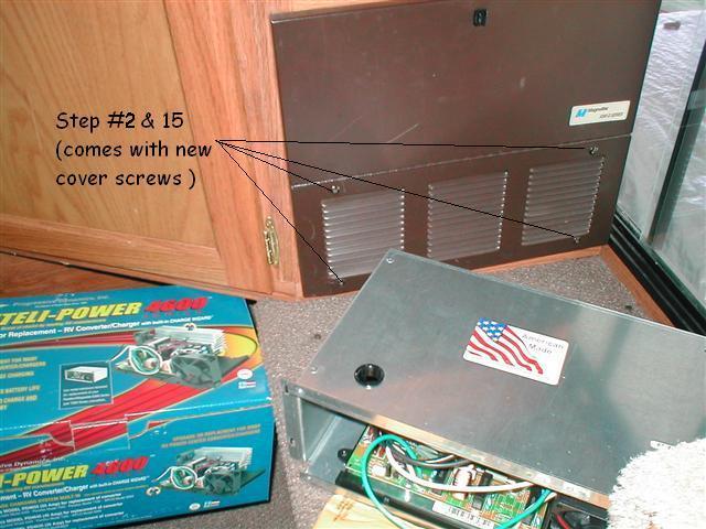
    2. Remove front panel by removing (4) screws at bottom of panel.
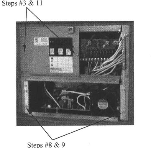
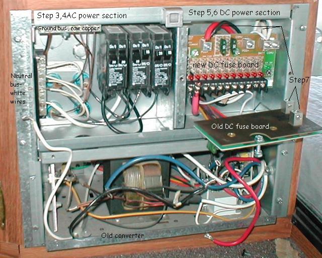
    3. Remove AC power section cover by removing (2) screws.
    4. Disconnect the neutral (white) converter feed wire from distribution block, and hot (black) wire from AC
        main breaker. Pull wires thru the hole at the bottom left of the AC power section.
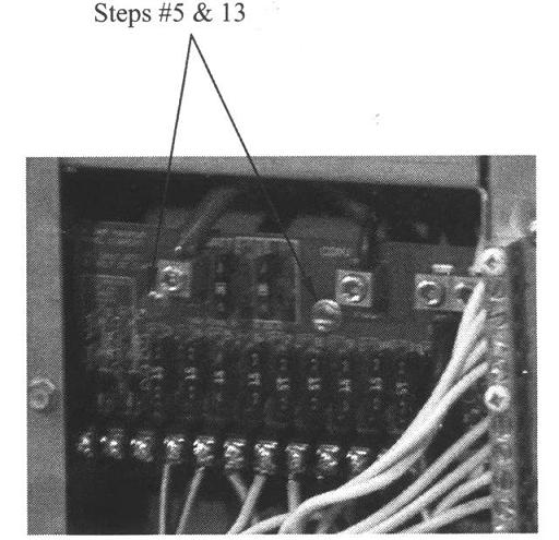
    5. Remove the (2) DC power distribution board mounting screws.
    6. Pull the DC board outward and remove the blue wire from the top of the board, and red and white wires from
        the BACK side of the board. Pull wires thru the hole at the bottom right of the DC power section.
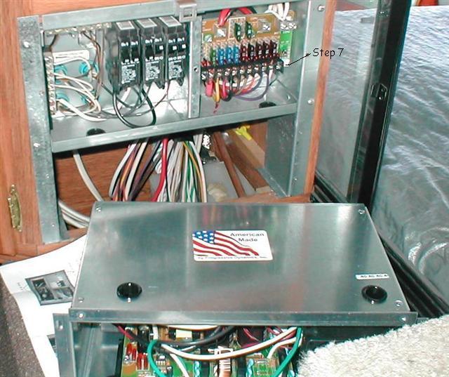
    7. Remove red wire from..the FRONT of the old DC board, and reconnect to the terminal labeled "BATT POS+"
        on the new DC board. Remove the white wire from the FRONT of the old DC board, and reconnect to the
        terminal labeled "BATT NEG-" on the new DC board. Transfer branch circuit wiring in this same fashion.
    8. Remove the (4) screws securing the old converter assembly to power center, and remove converter assembly.
    Installation;
    9. Slide new converter into power center. Route black/white/green wire-set into AC power section,
        and black/white wire-pair into DC section. Secure using (4) screws removed in step #8.
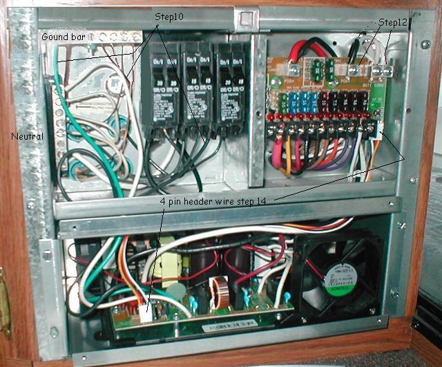
    10. In the AC power section, connect new converter neutral (white) wire to neutral distribution block,
        and converter ground (green) wire to ground bar. Connect hot (black) wire to AC main breaker.
    11. Replace AC power section cover and secure using (2) screws removed in step #3.
    12. In the DC power section, route new converter DC wires behind new DC power distribution board.
        Connect new converter power (black) wire to the new DC power distribution board
        terminal labeled "CONV POS+". Connect negative (white) wire to the DC board terminal
        labeled "CONV NEG-".
    13. Making sure new DC feed wires remain behind DC board, secure DC board to power center using (2) screws
        removed in step #5.
    14. Connect 4-pin header on DC board to 4-pin header on converter assembly using 4-wire harness (included).
    15. Replace power center cover using (4) screws provided with kit.
    16. Transfer DC Distribution branch circuit information to the new label provided with the retrofit kit,
        and adhere label over existing label on the inside of the power center cover.
        Affix green Replacement Notice label in any unused area of the power center cover.

Ooo kay... Here we go....Actually went very smooth-hardest part was feeding the main 12 battery wire behind panel to attach, which really wasn't all the hard. I do have a 10 gauge wire for refer, though-the fused connection screw is a bit small...

step2

What's more fun than open new hardware out of the box?

step

Here I've removed the 110 AC cover, removed the 110v wires (black & white) & pulled thru. Then I removed screws, pulled down old 12DC board, removed 12v battery wires (red,white) & connected to new panel per instructions. Disconnected red, white & blue 12v wires from old converter & pulled thru. [step 3,4,5,6,7]

step

Finished transferring all 12v branch wires and fuses ,step7. I recorded all the wire colors-fuse size, terminals numbers (both old and new) and service description from old label into the installation book. Was easier than removing one wire at a time. The 1st 2 terminals on new fuse board are 'low voltage' so it started with #3 on new board as #1 from old board. Ready to slide in new converter... [step7,8]

step

Slide in new converter, connect new AC 110v black,white & green wires from converter to 110v terminals per instructions. Route and connect new black & white 12v wires from converter (they come labeled) to new board per instructions. Plug in new header wire. [step 9,11,12,13]

LEDs!

Reinstall the cover/door. I pulled a fuse to emulate a "blown" fuse condition-cool. Each fuse has an indicator LED that comes on if fuse blows. The mode charge LED tells you what the charger is doing, described in instructions. Mode button (NOT recommend allows you to override ,see instructions.

LEDs!

I decided to put a window in my door so I could see the charge mode light without opening the door. I happened to have a 1" grommet laying in the shop. The led actually sets back almost an 1" from door; plus converter is down in a corner on bed step, so the light from the LED wont be annoying. This is looking straight at the door, you have to bend over to see the led.

LEDs!

All in all an easy replacement/upgrade.

Update: 10-09
I was one up'd- fella MTBob POST link on RV.net) posted how he made a sight glass. Clever! The grommet sorta worked but I had to bend over to see the led. Thinking you could mod the sight glass (plastic rod) for how bright it might be I decided to try. Found a toilet plunger with clear plastic rod handle, Series of bulbs at the end, 1" dia perfect fit. Cut off the end, polished, and replaced the grommet I had. Used O-ring hose washers to hold it in place.

sight glass

The light is fairly dim (couldn't capture with camera) which is ok but the bulb sticking out does glow (end is round so light reflects back on the sides)-However if you look at it, even a slight angle, you can see the led reflected inside. Kinda fun-sight glass. Spent more energy playing with the light than required to install converter.

Back to Ourelkhorn Camper Modifications page