Add PWM speed controller switch to Campers Bath Fan
Intro This section and what Im doingRemote PWM/switch box
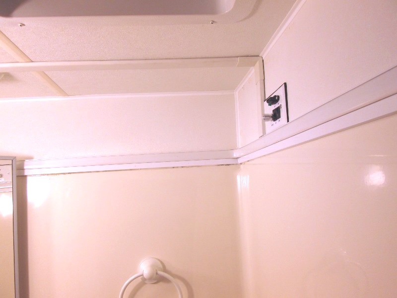
Run wires from vent to new box
Mounted
Primarily to slow down & quite fan it also adds variable speed instead of single speed. Additional plus is fan will consume less power with PWM at slower speeds verse stock. I had added one to the stove vent and one to our Fantastic 3 speed fan.
Second is mounting new on/off switch and PWM controller in a box to lower making easier to reach. Will also give some protection of the PWM controller not being exposed directly to outside.
And third, and real motivation; in the near future will be replacing this fan with a Heng's Vortex I upgrade fan. Larger fan that draws more air, and a lot quieter than the stock buzz & whirr motor. The Hengs Vortex I single speed fan upgraded with this PWM will make it variable speed, reversible and less cost than Hengs 3 speed. Again- adding the PWM controller other than variable speed and reversible is the power savings. Wont cringe when I have to turn it on when on battery.
So this page, as mentioned, Im adding/mounting the PWM controller and switch to control the fan remotely. Or simply pre wiring. When I order new replacement fan,it will simply be a swap out as wiring will be done. The Hengs Vortex fans basically replace the existing vent fan. You remove the stock screen from roof vent, connect the wires to new fan and install in just like the screen had been. All from inside the camper. The Hengs Vortex fan are NOT a Fantastic or Maxxaair as far as quality or sound- they are inexpensive and do work at about $40 compared to $140-perfect in the bath. Meantime I'll connect new controller to old fan
- PWM/switch box
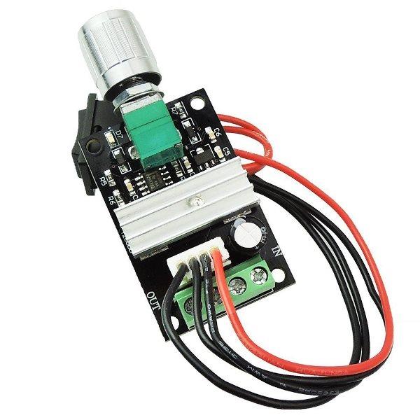
Similar to the $8 PWM I added to stove vent (Amazon link) I found 2 PWMs for $11, so search around. Many vendors sell identical controllers. Has remote reversing switch that plugs into board. Amazon Links good for as long as they last.
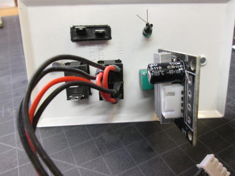
1st Issue is this PWM is 2" deep or needs a box that deep. So using a surface outlet box Sigma 14250WH. It still requires me to modify the PWM board as wires exit opposite end. What I did was de solder the terminal strip, I'll solder short lead wires directly to board. There are available controllers that have rheostat/speed adjusting knob that are not mounted on board, would simplify but having already used this board staying with what I know works.
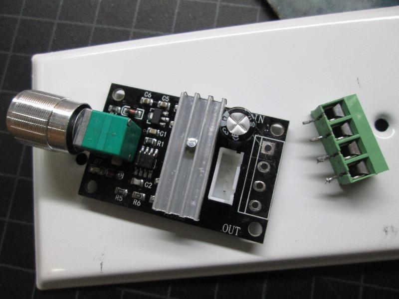
Terminal block removed-takes a little time slowly pulling while heating solder till it clears...Clear holes in board with small drill bit.Tested to ensure still works...
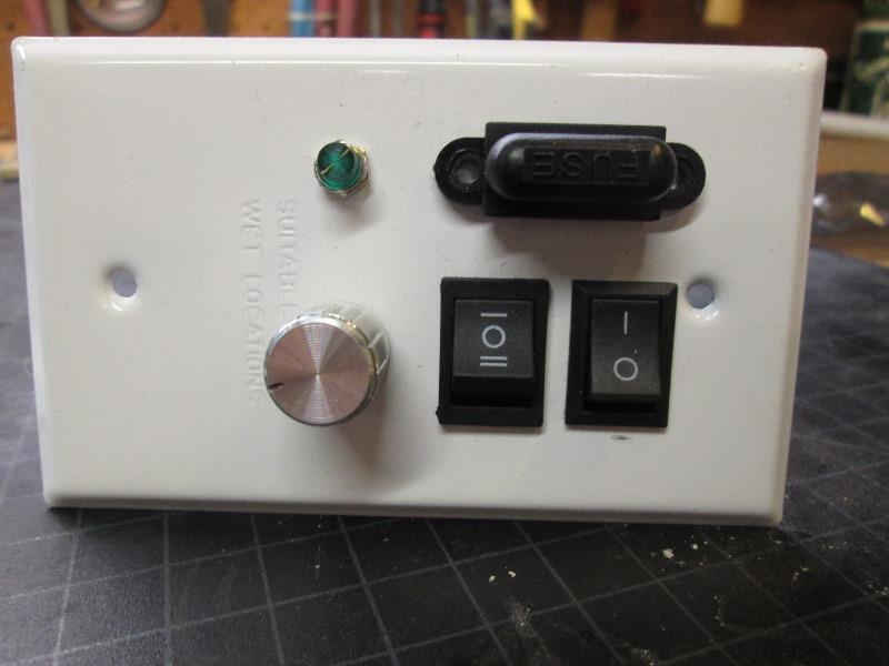
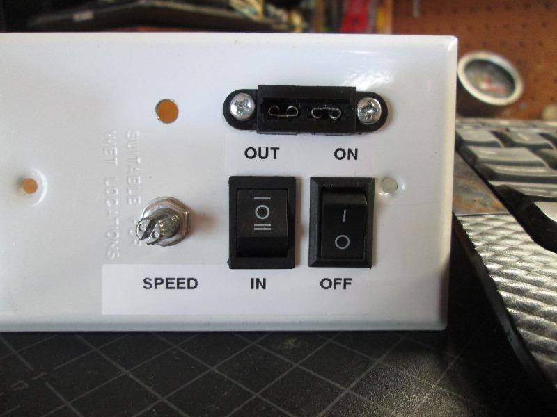
On to mounting components to blank metal cover. Hole for PWM rheostat knob, PWM reversing switch, adding on/off switch, pilot and fuse holder. I'll note these do have an off position between reversing switch positions, also the output/speed adjuster knob has an off position. HOWEVER these turn off the output of board, board is still energized, though slight milliampere if powered. I want positive off when not in use. Have enough parasitic drains...
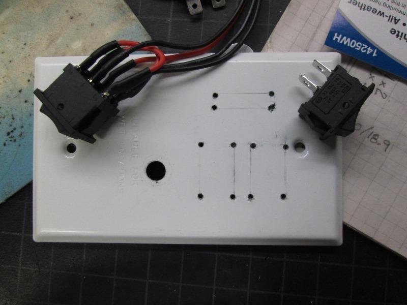 Drilled holes in corners, only had one drift off at screw hole---
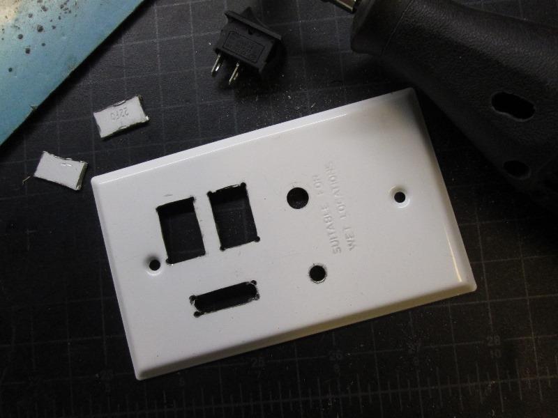
Used dremel to cut then small files to clean up
Well, that'll work...
Wiring going to be fun. I think on this one I'm going to wire the neon pilot to motor out put as a visual when adjusting motor speed
Labeled...
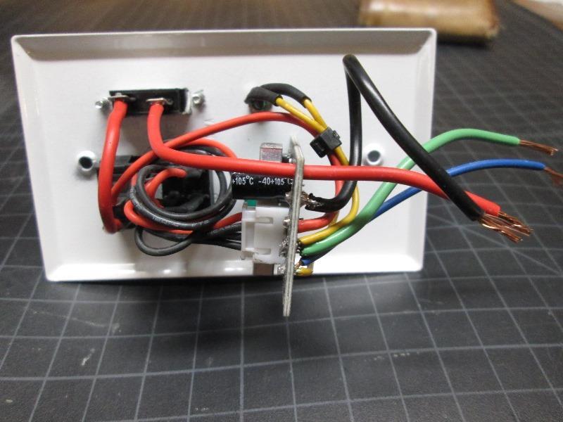
Wired. Short leads will allow hookup to wires run from roof vent. Ideally they would have been soldered to board but that would have been painful. This will make removing if needed simple. Red & black to camper power & ground, blue and green to vent motor with Yellow leads to pilot. Neon (not LED) pilot (polarity doesn't matter) will dim/ brighten with speed adjustment in either in or out position of fan motor. +12v in goes to fuse then thru on/off switch then feeds board. (Red wire thru board temporary)
Noted which board terminal is positive when motor reversing switch set to out, solder the blue lead to it-so when I wire motor I have a chance of getting polarity correct.
- Prewire and box mount
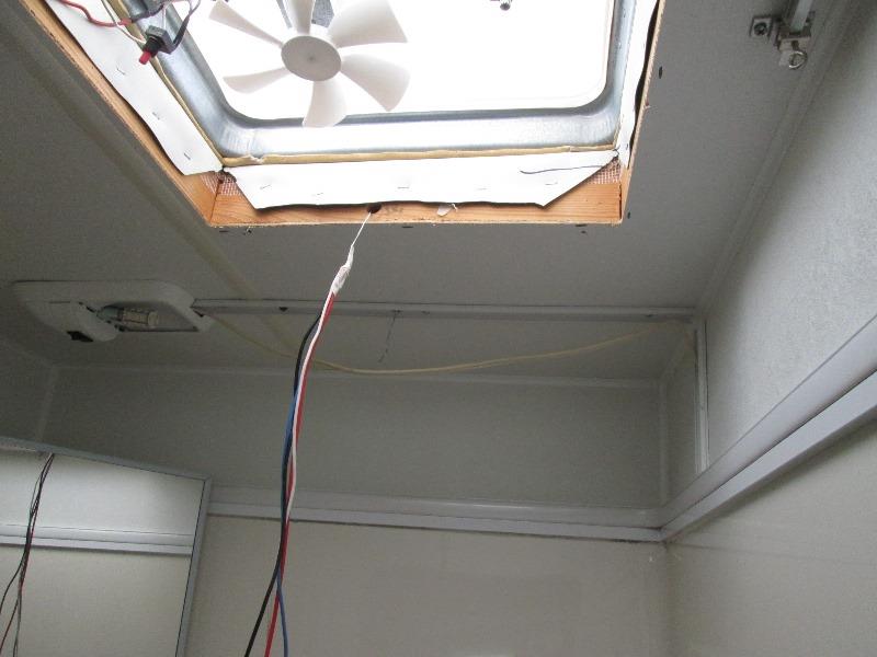
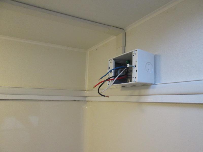
Running wires to new box location and mount box. Getting from vent to new switch location, or into existing wire loom, required drilling 2 holes. One thru side of vent framing and another thru wire loom and ceiling. Only about 12" so fishing wires pretty easy.
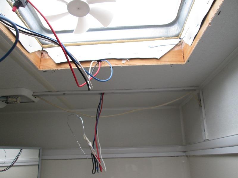
Wires pulled. Box will be mounted on wall just above shower fiberglass beside the wire loom.
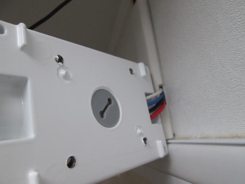
Cut a notch in the wire loom base and clip on cover. Wires exit loom and go into side of box just back of the threaded romex holes (not used). Box stand off allow wires to run under before going into holes I drilled.
Can almost see wires thru drilled holes. Once box mounted wires cannot be seen. Snapping on the last cover piece
Box mounted. Much easier to reach without looking straight up. This is just above the sink. Before, as our vent is close to door, you kind of had to bend over backwards once entering to switch fan on. Appearance wise would have been nice to flush mount the box, closet is on other side of wall so doable. However there is a 1x4" cross brace at top of shower. Not wanting to cut hole possibly weakening structure went with surface mount. IF it becomes something cant live with, redo would be simple enough. RAAAAATS....
- Well a little later.
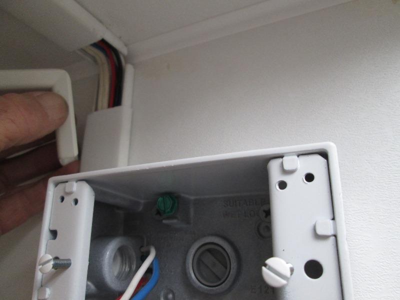
So apart it comes. Cut hole thru shower side wall to clear components on face plate. Drilled corners thru to mark paneling on other side in closet. Opened it up. cut thru to inside of closet. Box I'm using is 1 1/4" deep. With face plate cover flush mounted end of PWM board is 1 7/8" protrusion so only sticks into closet about 1/2". Box on other side of paneling gives me plenty of room for needed depth. Removed short section of wire loom cover, drill hole thru to reroute the wires into hollow wall.
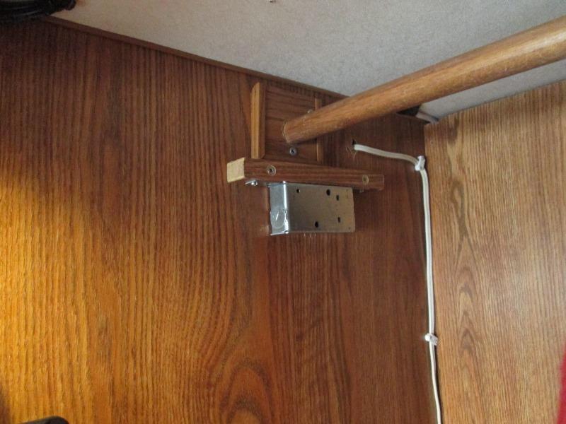
Using a standard box with rounded corners so protruding end into closet doesn't catch clothes. The new box only acts as a cover. Pieces of 1x2 glued in on either side of hole to mount box, drill box and screwed to 1xs. Run wires into wall and over to box connected the new switch.
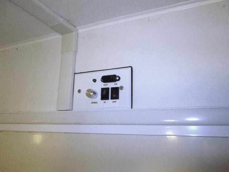
Mounted...To do-Paint the screws-done
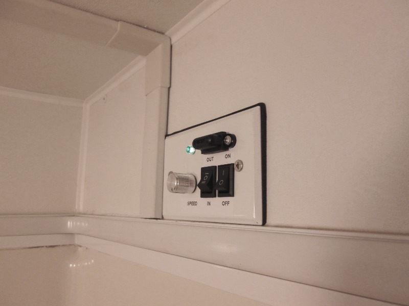
Nice, evacuate the bath moisture humidity when hanging wet stuff without the roar, or full bore for steam.
Worth the redo. It is a lot easier to access the fan switch with it on the wall. Ready for new fan.
More pre-install, Relocate crank handle on vent to move knob away from edge of new Vortex fan. New Vortex 1 fan installed
Back to Ourelkhorn Camper Modifications page