Add USB charger ports at camper dinette table
Part 3 of dinette mods, in progress...
-
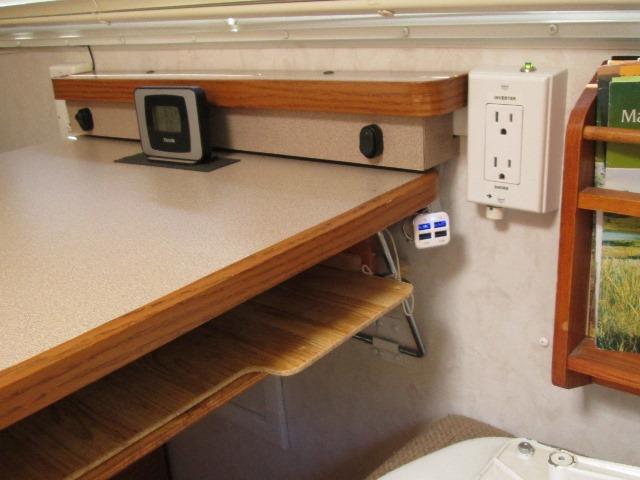
Simple, but went round and around on this, adding USB charger ports near campers dinette table. Its where stuff is charged. Usually we run inverter and I recently added another 110v shore/inverter split receptacle for convenience. But as most items will charge directly from 12v, seems silly not to have direct 12v access also.
There are some nice USB chargers and a lot of different styles available. I would have liked something with a meter, switch to turn off and of course USB outlets. I was leaning toward some of the panel types but where its to be located can't flush mount (solid shallow wall). Found a 'tent' type, basically a housing to mount the panel type in but it would have to set on table, it needs to be removable. Doable but I finally decided to simplify.
Using 12v power outlets (cigarette lighter receptacle style) mounted to wall under table with simple plug in USB chargers.
One reason chargers easily replaceable, can use the power outlets for some stuff that has lighter male plug like RC chargers, small fan etc. And simpler to locate and wire. Picked up a couple of surface mount 12V outlets that have mounting flange from local Autozone, Bell 12v power outlet 05349-8
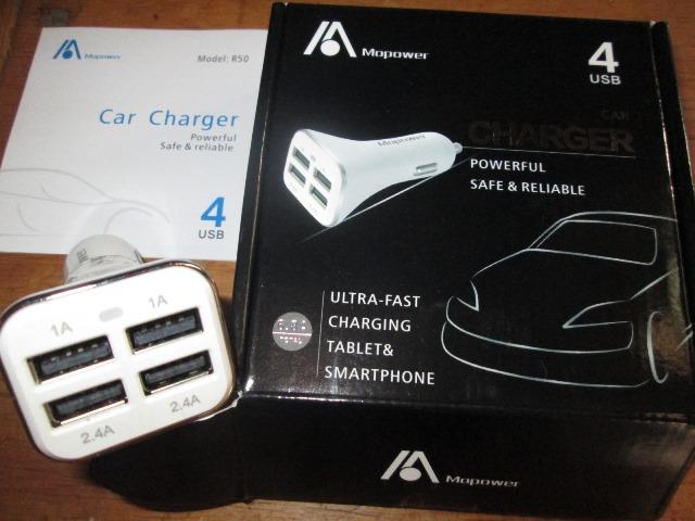
Ordered charger from Mopower, mostly because I liked the square face but has (2) 2.4 amp, (2) 1 amp USB ports and white. Plan is to mount to wall under table with just the face protruding
Next is getting 12v to dinette.
I was going to run a wire from the converter as there are a couple of unused circuits. Make the 12v charger circuit separate from everything else. Not going to be fun to run wire from inverter across camper, over water tank, under slide up thru dinette seat box and up to table. Getting ready to run wire I'm staring at the converter. Just getting wire to back side to fuse panel...err...then I noted the heater fuse. Hmm, we removed heater a long time ago, we use a catalytic heater. The heater was in dinette seat box. Opened up box sure enough there's the wires.
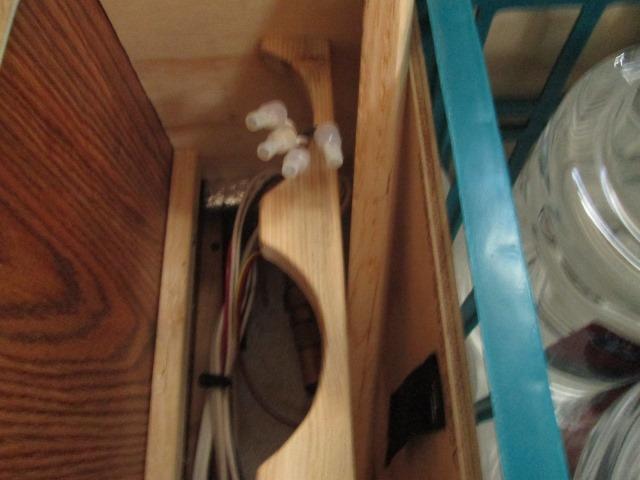
Fuzzy picture but 12ga power and ground wire terminated right there in the box. Curious what else is might be on this circuit. Removed heater fuse found everything still worked so nothing else on this line. Wow, I can use this to feed 12v receptacles. Short run up to table, be a separate circuit for USB chargers on wired 12ga 15amp circuit. No crawling around routing wires...makes it easy.
Along with the previous heater power/ground wires are 2 smaller wires that ran to thermostat. They run to where our solar controller is now located. Might later see if might use to wire a remote meter for solar controller-that would be nice.
Not sure why I checked but I cut off the crimped on wire nuts to verify power and nothing. Nada. Zip. Checked fuse, outlet terminal good and showing power. Recheck wire in seat box- nothing. Between fuse and seat box is a break-GREAT!. Decided though might be easier to run a new wire- I need to know why heater supply no longer connected or where. Ground wire shows continuity.
Found a plug under slide that wires from dinette box leads to. It showed continuity so break isn't in routing from dinette to under slide. Then working from converter side found wire from fuse that's routed under sink cabinet to water tank box wire loom- 12" as the crow flies but probably 3' of wire to get there. Nope we have power. So down to somewhere between top of water tank and plug under slide-there's a break in what should be continuous wire. Checked where wire exits water tank box and leads to under slide- nope no power so break is in the length across water tank?
I can see it all except where wire is wrapped under bottom of bundle.
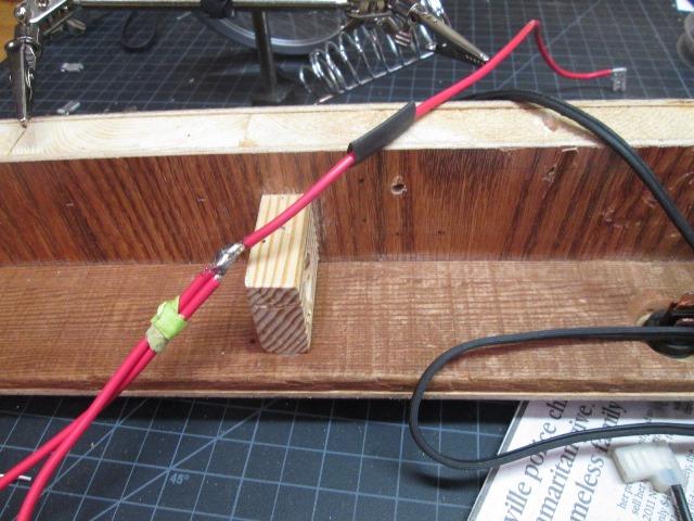
Cut the electrical tape to pull the wire around the bundle and it came out in two pieces! Well, There's the problem!
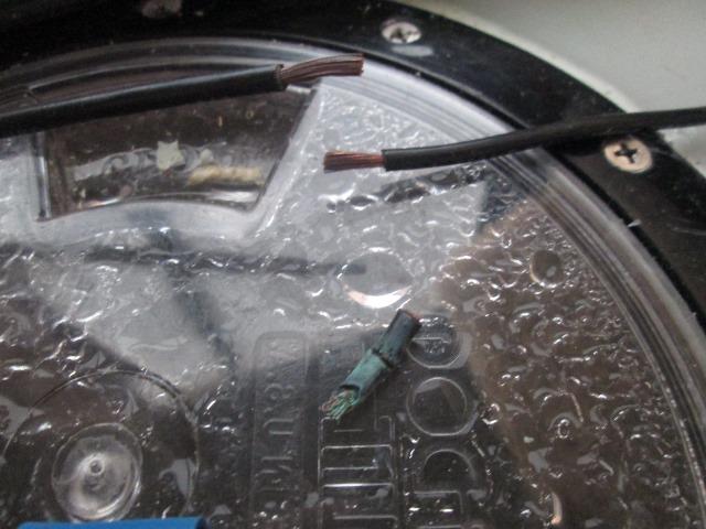
The short section that was under wire bundle is coincidentally centered over tank access lid. I assume that way back when access lid installed I nicked the wire. I did have a slight leak on lid when tank was full, since fixed but I guess it had gotten wet long enough to corrode in two. Or possibly because window is just above, condensation keeps damp enough to cause corrosion. At any rate the corrosion had gone into wire a few inches so I had to pull & reroute wire to get enough to cut back to clean wire to rejoin. Yup -spent more time than running a new wire, but fixed.
Visually inspected remaining wires in loom. Cut some plastic strips to elevate above water tank surface
-
Ok we have power. Within a few feet easy to connect.
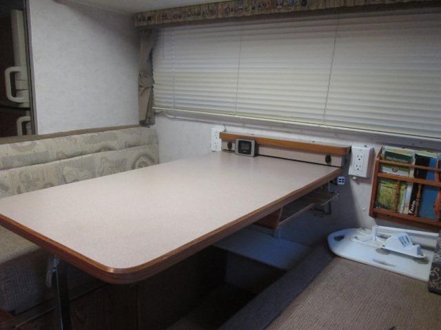
Spent quite a bit of time locating the receptacles with chargers. Best I came up with though hard to see with table removed is just under table. Made some small wood wedges to angle chargers out a bit and slight upward tilt. Will place just below table protruding slightly but pointing to where they can be seen to plug cords into.
Wiring will be straight across under table using wire mold to cover. Need to run down to seat box. Nice 14ga wire on receptacles but would have been real nice if supplied wire couple inches longer. A junction box centered to make connections between the two and supply wire. Suppose I can just make a short jumper that would plug in. Also want a switch on this, so run supply hot up above table, back to receptacle leads. Not sure what type of switch that will surface mount and hide wires.., also seriously considering adding timer so we can charge a few hours during the middle of the day to utilize solar output when not there. Timer would turn off if we don't get back and still leave battery charge time. So completing wiring of the chargers on hold to I figure out how I want to finish. Timer could be in seat box and done later, so its coming up with switch and routing wires.
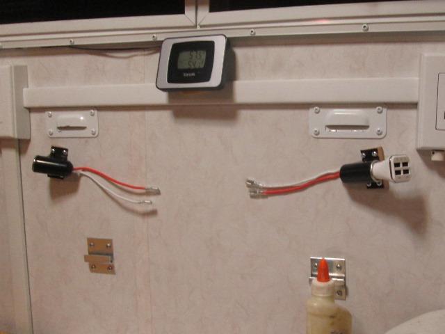
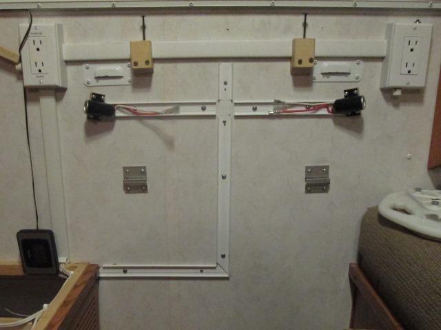
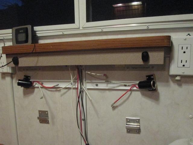
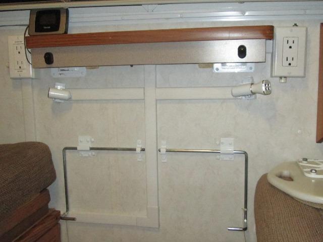
Meantime I removed the receptacles.
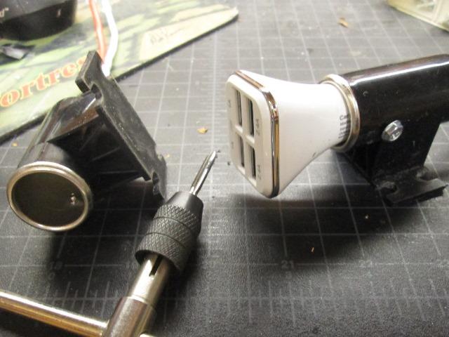
One problem with the plug in chargers- at least these, is they like to work themselves out or just unplug removing USB cord. I drilled and tapped for small set screw. Screw just long enough to seat and restrain charger. Simple and effective. This one, primarily for charging, it'll stay tight . The other will get a charger but needs to be easily removed for other use. May put a thumb screw, though don't know how long threads will hold up being used frequently, need a plan B.
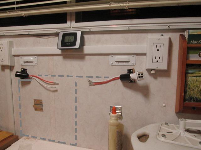
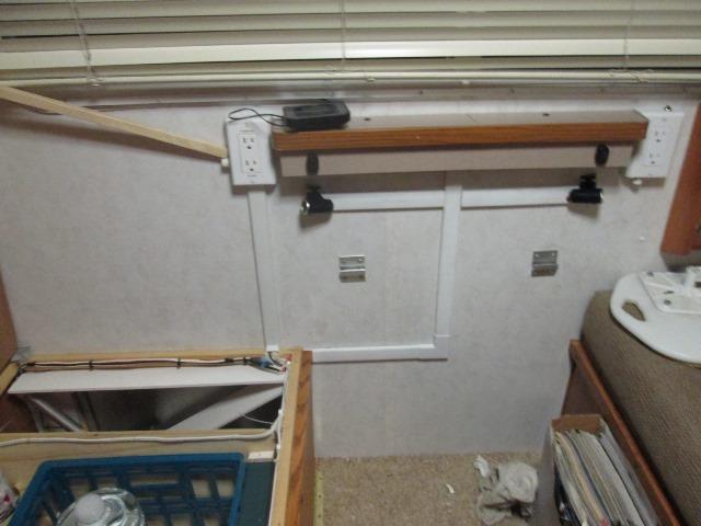
Well I'm sure there are others smarter than me if looking at picture would have seen what I hadn't. Laying out the wiremold channel, getting ready to wire, I realized that it can not go straight down. The steel support hoop for table spans across and sets in the two wall mounted clips. Hoop actually extends about 1 1/2" past either clip. Err this is becoming a pain.
Means wire cover will need to go down over at side as sketched in. I'm already not happy with the horizontal piece between added 110v box just to save a few bucks and ease of install. If not for holes left behind I'd change, go straight down into seat box like original. Now a second visible piece beside the other vertical on the left...starting to look like dog poop...And kinda stuck. I'll have to notch the wiremold to partially cover bases of receptacle in order to get past and still be high enough to get wires inside. Use ell to turn down into seat box. It'll work- not what I wanted to see-at all. So project sets, hard to proceed knowing what end results are going to be.
- This is me talking to me. I haven't found a switch that will work. This seemed such a simple project to start...but stumped. I'm adding to this page in hopes something will congeal. Been 2 weeks, every couple of days I wander out to camper end eyeball it for a while like some brain twinge is suddenly going to make it oh so clear...... I have decided a small white shelf to set between the 2 plugs on top of wiremold might solve issue of me wanting to remove. I think will help 'neutralize' visual appearance that makes me want to rewire the plugs. But later-maybe. It would give me more options for mounting a switch. I'm also toying with the idea of ignoring the steel hoop that's preventing continuing as planned. Really want the wire mold centered somewhat going down so it virtually unseen.
I'm seeing a few options on the hoop. And writing this came up with solution..
One is couple of sash or table leave locks, even simple slide hasps could replace the hoop all together. Easily support table. Pretty sure there is sufficient backing in wall. When installing the receptacles the top screws bit into aluminum frame. Not looking to reinvent the wheel though...
real first thought was cut a section out of hoop. It may try to bend or flex with downward pressure on table. I honestly don't think it would. However two small aluminum pivot blocks would fix. The cut ends stuck into them could still pivot, restrain from flexing. easy. Pin or add bend to ends so the now 2 separate pieces cant 'walk out. Pretty simple really but I don't want to.
Simpler is to just weld a piece of rod between and on top the cut halves, bridging the cut clearing the wiremold. Id place as high as I could in hopes when table pivoted down it still wouldn't hit the wiremold, however if it did easy to pop the hoop out of wall clips.
Possible as it only needs another 1/8"-3/16" to clear wire mold is heating and stretching and bending a hoop midway between. Umm 1/8" to 3/16":...
2 simple square spacers placed under wall clips. Good grief...that simple. The long way round.
Last issue is the switch. As the chargers have pilot lamps, though in milliampere, needs to be turned off when not using. Power lead should run directly to switch then feed receptacles. Just unable to locate a surface mount switch that 'fits. I could wire, utilizing quick connect plugs and if I find a switch splice it in with plugs. Or stub wire up in hopes of finding switch. Could add the switch on seat box, really simple, just wouldn't be convenient. If I were to do the timer all I'd need is small momentary somewhere but don't really know that I'm going to add. And it would be later-separate from this install.
So that's where were at, I'm proceeding with original plan and run wiremold down and start wiring. Deal with reinstalling table when done.
-
The thought about adding a small shelf between the 110 boxes, though not part of this, kept creeping up in the back of my mind. If I did make shelf I could add a lower face to it, put switches in it. That would allow use of any toggle/rocker switch & hide wires...ohh...
Then I remembered having old raised surface mount switches from back door. They are white.
Dug them out and threw some ideas around. The panel and raised box isn't usable but the switch is. So a simple shelf maybe about 3" deep, out of 1/4 material. Face maybe 1/4" wider than this. Post mount switches would simplify most rockers use square hole, finding white even more difficult. These are a standard RV part so replacement that fit would be simple. As it happens this is a double -it occurred to me I could add switch for each receptacle.Single wire running up behind face to power, wire from each switch back to single receptacle. Seems be easier to wire. I could run the ground wire up, loop for now but split to return to receptacles. Then if I find an amp/volt meter that isn't lite up like a Christmas tree I could add later. Hmm. So I guess before I get too carried away I should cut the face piece-see how difficult carving a hole for the panel mount switches is. Then details like how to mount the shelf.
Coarse figured out building shelf to have a place to mount switches kind of self defeating. Though really hoping to make the added 110v receptacle and wiremold running between not so tacked on looking- I could use to mount a flush panel for the USB ports like I wanted in the first place. Oh well. We will be adding a USB port by the bed later for charging, cant wait as that will be cut a hole and screw it on a panel port...
Just looking at the table & the shelf I'll be adding. Took some measurements- trying to see how this will all go together. Chicken before the egg...
Shelf will sit on top of wiremold channel, full length between the plugs. To the shelf will be a skirt set back about an 1/2 and hang down 2". To the skirt will be mounted the switches. Skirt will hide what's behind. Also will limit access. So..plan is to make the shelf & attach shirt (after cutting switch holes. Take to camper get some closer wire needs laid out then back to shop.
Shop install the switches and wire them, making allowance for any future additions, meter etc. The shelf will be pre wired with 2 hot leads from switches to plug into USB ports leads, 1 hot input to switches from source with a stub wire & ground stub lead for future. Run hot & ground from seat box to USB wiremold. Hot will terminated with plug to plug in shelf/switches assy. Ground will tee, leads to USB port and 3rd plug for/from shelf. Sound confusing but pretty easy. What it does is simply let me hang the shelf with switches pre wired then plug it in. The trick will be staggering the plugs to get it all to fit within the wiremold channel.
With that ready to proceed with shelf. Didn't get far. I was going to use pre primed wood and shelf would be white. Thinking it would blend with what is already there. Holding up material to mark, it does tie wall white but what you really see is the shelf extending out over table. The white just looked..odd. I almost shelved this whole project but then recalled having a piece of the old counter extension table. Same formica as table.
Holding up old table piece-no question, that's what were doing. I'll still use white for skirt but shelf itself will match table.
-
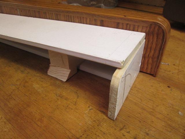
Easier said than done. Old shelf has quite a bit of taper plus I only have a bout a 12" square left. Considerable effort to cut, splice and fill the hollow halves to make a 24" shelf. As I don't have any of the original T molding I'll use some vinyl to cap the shelf edge.
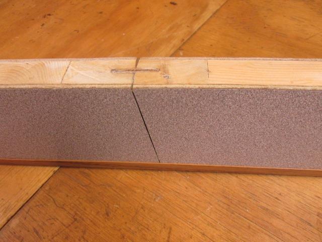
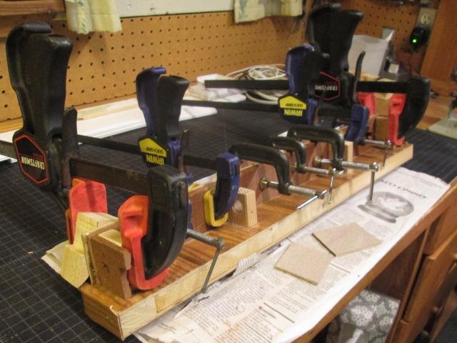
I used the original trim groove to join the halves inserting a full width piece of 1/8" plywood, lathered in glue. Few staples into joints, few toe joining halves. Clamped to couple of framing squares set edgewise, ensuring it set up flat and back edge straight. Left it over night.
What I was greeted with as you can see above and below..I don't know how it moved but the joining edge there is almost 1/16 gap. Oddly its still flat and square. All I can think is the joined pieces swelled pushing apart. Its not coming apart.
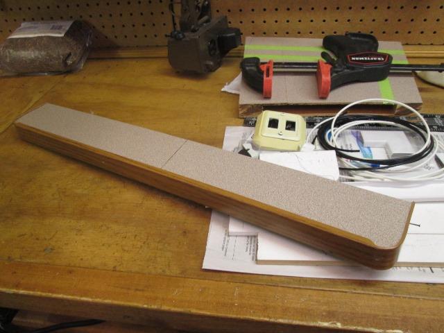
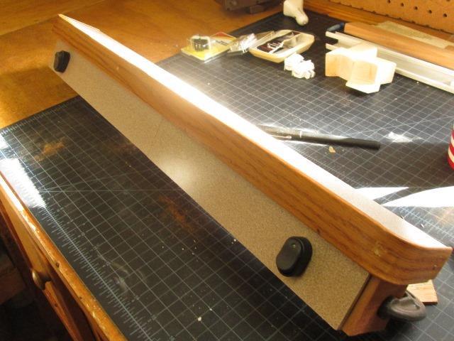
Trimmed 1/16" off one end and cut a 3/4" radius at outer corners of shelf. Wrapping the channel around proved impossible. Tried several ways but finally trimmed top & bottom legs to 1/8" wide. Used heat gun and got it to conform. Looks pretty good. I may or may not trim remaining front top leg same width. It looks better but I've no more material-do I chance ruining it for a little cosmetic-na I'm done
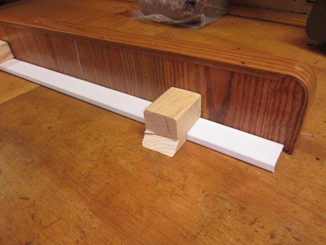
Cut the blocks that will be screwed to wall. To these the shelf will be screwed to from top. Notched to bridge wiremold cover, bottom edge angled for table removal. Note the skirt will also aid to counter leverage movement, Though shelf is only 3" wide, no weight. I may if it seems it wants to move is add 1x2 blocks to wall behind skirt and use couple of small screws. Likely not. I will drill some angled holes up thru bottom to run screws into wall thru shelf.
The existing wire mold cover, now totally unneeded, will slide off if I removed left box. Absolutely no reason I should have to get inside but allowance made. I could cut a few 2" pieces to replace the full length cover, place behind shelf supports and at ends where its visible. Could. Actually now that I'm thinking out it I'll remove cover cut in to 3rds. Center section could then pop off & ends slide to center to remove.
Laying out skirt
Well just scraps to see- skirt will be 2" wide. Cut some 1x2 blocks glued and screw to bottom of shelf to attach skirt. Obviously look a lot better once I actually made and prepped. But to me, obviously this will still look like pooh when done. So stopped again. Got the method but need material. I have just enough scrap formica left to face skirt. I'll go ahead and make a white box. Then I'll cut the formica- If I chip or break it I'll finish the white box. go back to white box.
And the plan changed yet again.
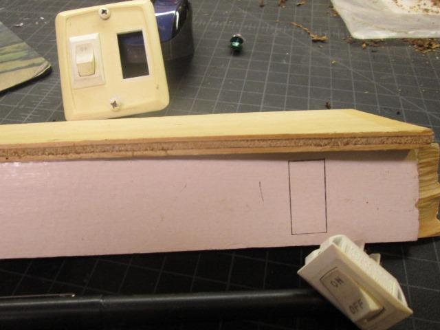
Used some 1/4x4 1/4" lattice I had, split on table saw. Cut a few blocks to support. Holes are to run/support wires. Glued and stapled it all together. Was able to successfully cut formica, piece just in the foreground. It is already glued to some 1/8" luan. Ran masking tape on cut line, cut face down with 140tooth plywood/laminate blade, very slowly. I don't know that the masking did or didn't help against chipping but figured it couldn't hurt. It came out pretty clean.
Glued and clamped the face with a 1x2 back up to even the clamping. Still, I added a few more before letting it set over night. Glued the end pieces next morning. Getting ready to install switches so I can pre wire. Cutting square holes, hmm. Problem is thickness, Switches cant use more than an 1/8 and snap in so I'll need to clean wood from back side. I was going to cut backing with larger square before installing the formica. Didn't. I've decided drilling a hole verses trying to fit a snap in a LOT simpler. And a lot safer as far as one time chance on the formica.
It was. Though I think the snap in would have looked better I couldn't justify the time. Plus I can now use any threaded stem switch, well most. I may get flush push buttons later, not liking the black switches. I still had to clean material from back to use the short stem switches I had.
-Wiring
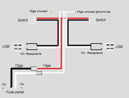
Final simplified diagram. Left side 12v receptacle eventually will be used for a plug in DC charger for my laptop. It requires 19v@4+amps, doesn't use USB/currently use inverter to power its 110v/19v 'brick'.
Solder branch 'tee' for the incoming hot to split and feed switches. Continuous 14ga red runs to left switch with soldered on branch running to right. This will run to seat box and terminate with male bullet. Hot source,(12ga black in seat box), terminates with female bullet.
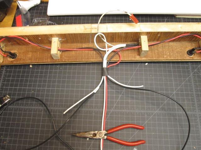
Bit later and wired. Used flag terminals on the switch ends for more room to install/remove. From the switches back to 12v receptacles used 14ga black for power. The possibility exists I may add gauges or need power in shelf for something else. If it needs constant power I'll tap red wire, if to be controlled by switches, black. Hence the black and red so I can see what's what.
Same with the white ground wire. I could have, and planned, was a branch tee and run directly to receptacles. But running up behind shelf and then down allows for possibility for anything added. Did make it a bit more difficult. The incoming ground I left a large loop. This could be cut to splice in ammeter or other meter. Also lets me easily see which white wire is source. To its end is bundled grounds. I added a 3"blind lead for easy ground tap/use if needed, a 16ga 6" lead that terminates with female spade, just in case I decide or need to utilize the switch pilot lamps, Then 2 leads going back down to receptacles. Running ground up then back down with individual leads also keeps wires from crossing over each other at the lower wiremold junction, better fit inside limited space under cover.
All I really did here, beside just wiring the individual switches to control receptacles, was to try to foresee and allow for future wants without having to rewire anything.
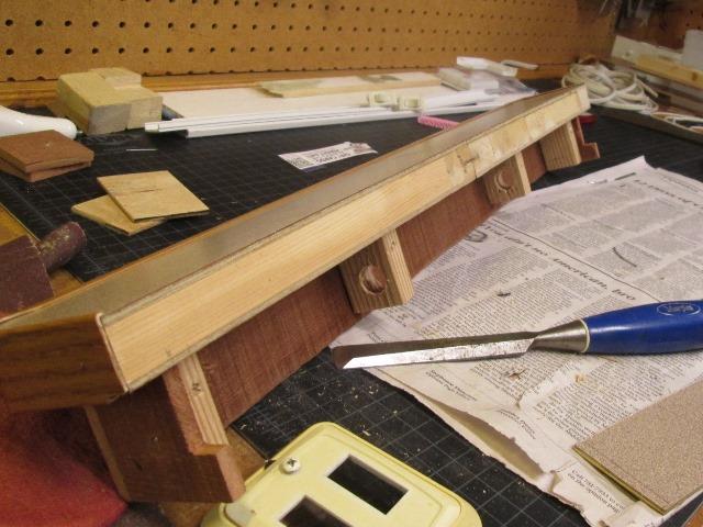
Wiremold base laid out. Using an ell at bottom, at receptacles cross junction I'm just cutting/clearing the sides of vertical base and cover to pass wire.
And in the process. Cutting wires to length, add terminals and shrink wrap, mostly as strain relief for the crimp-on connectors. I have a ratchet crimper which makes pretty clean & secure connection but...I use a smaller diameter of tube to slide on wire and inside the crimp on sheath, then larger over terminal and wire. Minimizes any flexing at joint. One odd thing I noted is the receptacles have covered female terminals on both hot and ground. I always, when using disconnects, keep the possible live end protected with the female side and or covered end. My first impulse was to cut off the terminals on the receptacles hot leads. Instead, just slid back the covers, used covered male ends on the positive feed from switches Works if these were plugged into something but generally they are wired at end of line-just found odd. Anyway. came out pretty nice for something you'll never see. Unfortunately, I thought I had, but no picture off completed wiring.
Added the terminals to end of red & white, plugged into seat box leads. Some creative trimming on the wiremold covers at receptacles. The leads kind of S back under housings. Zipped up the power leads inside box. Here I've propped up a board underneath. As the end part of seat box is accessed from outside I'll cut and staple something up to protect the wires from me enthusiastically retrieving or putting stuff inside.
Now to see table back in.
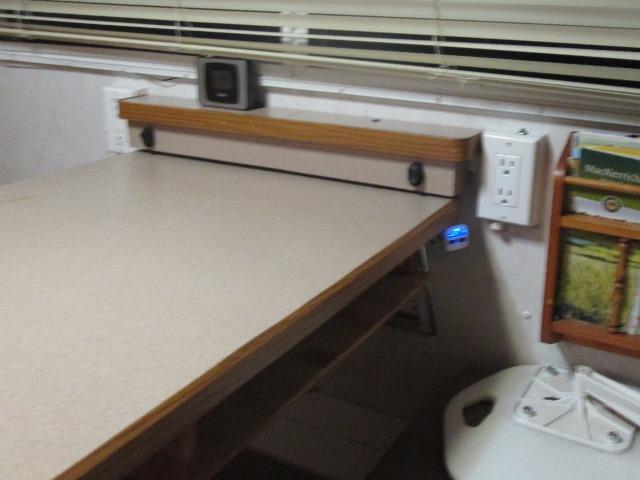
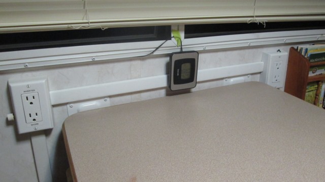
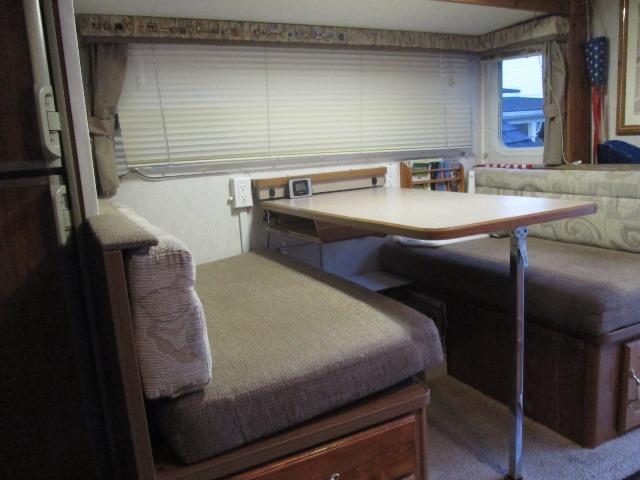
Fuzzy picture but it works.!
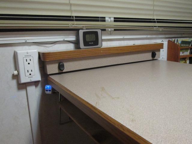
Hmm maybe camera didn't like the cold..But as convoluted as this simple install became really liking it. Shore or inverter 110v, 12v and USB 5v charge source, from either side of table. Shelf, though to have place for switches, I think looks better than the wiremold across the table top and hides the tables brackets. Black switches sure stand out, easy enough to change out if I decided to. Course now that its buttoned up I should had run the thermometer remote lead in wiremold, though I don't really know what I'm going to do with it. USB ports done! Surprised how bright they appear in picture, actually pretty soft LED, Now to address the tables support arm that wont go back.
Well since everything is already out decided to cut the seat box 1xs that table sets on to make a bed. I had added a shelf to underneath of table top to store laptop, I know table wont fit any longer.
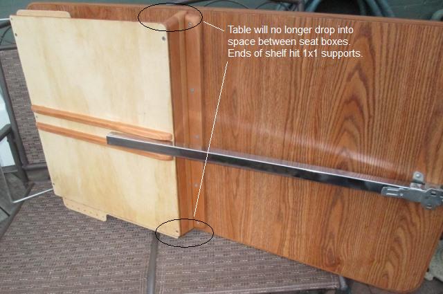
Just requires a simple removal of 2" sections from 1x1" supports where shelf ends are just a tad wider than space. Not that we use it but I'm here...
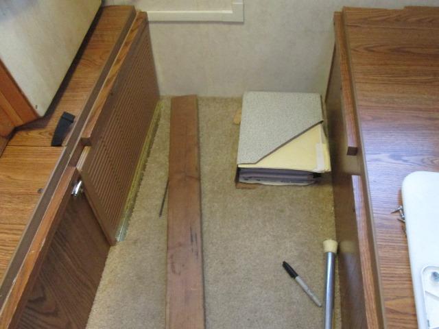
Marked where the shelf hit in center of the rails, removed, cut and reinstalled them. We never use this as a bed-but ya never know.
Sat the table down, it clears the shelf edge but STILL wont fit. Err. Years ago I hinged both seat box lids. The piano hinges pushed them out. Space between is too narrow for table width. Oh well we don't use as a bed. However bugged me I defeated it...
Decided as I already made a little effort to make work a little more would make it function. As its only about a 1/4" too narrow I remove the hinged and fixed lid from the left seat box. Ran them both thru table saw. The hinged side took another cut to get enough clearance for table top. That left the groove cut in edge of lid too shallow to reinsert trim. Back to the saw, re cut the groove a bit deeper. Reinstalled the lid, table fits.
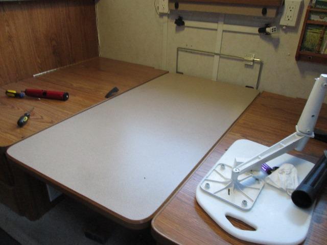
Wow...functioning dinette bed. I'll have to make myself sleep on it one night to justify. 10 minute cut end up 2 hours. Curious, I just went back and looked. The lids were hinged back in 2006, means dinette bed has been unusable for almost 10 years. Where was I...
-
Now to get table to work as table.
The table support arm will not set as it did before spanning the 2 lower brackets due to wiremold. I thought it was going to be a simple matter of just spacing out the brackets. But the 3/8" really changes the vertical distance a lot more than I thought. Not going to work. The original idea of cutting the rod, adding a piece back to 'bridge' the molding wont work either because bridge would be on outside. When table lowered for bed, the rod rotates over & down with ends pretty much vertical, bridge would be on the inside toward wall, hitting the wiremold. So the table wouldn't set flat.
I could cut, add the bridge, when needed as bed (never) could just remove the arms. They come off pretty easy, well not easy but they do. But another idea struck me. If I cut the support rod, removing a section to clear the wiremold, I 'could' add another pair of brackets upside down to capture the free ends. That would work well, table would swing down as its designed, clear wiremold. If I cant find brackets or make something.
So with options, just cut the table support rod, removing about 1 1/2" section, Table now functional. Weight on table does cause support rod free ends to flex a bit, though usable for now just need to be careful. Need to address, soon.
[update-brackets found-- AP products 013-960 (or 13960) RV Hardware Table Hinge Bracket Kit, prices all over the map but under $10 a pair]. But I ended up modifying existing brackets.
That works. Cut off about 3/8" strip from existing brackets. Drilled and mounted. Placed screw in now uncovered & unused holes. When/if I get some additional brackets I'll replace the outer brackets, move the cut ones to center replacing the 3/8" strips. Maybe, at this point it would only be to use/cover original holes. The 'hiding' screws look a bit dorky. Functionally wouldn't really be much stronger. Masked everything and painted. Never did before because the rod clipped in from top, would have just scrapped off paint. Now the 2 halves can slide in. Once everything back together I'll mark the rods, drill small holes to insert lynch pin so they can't slide out on their own.
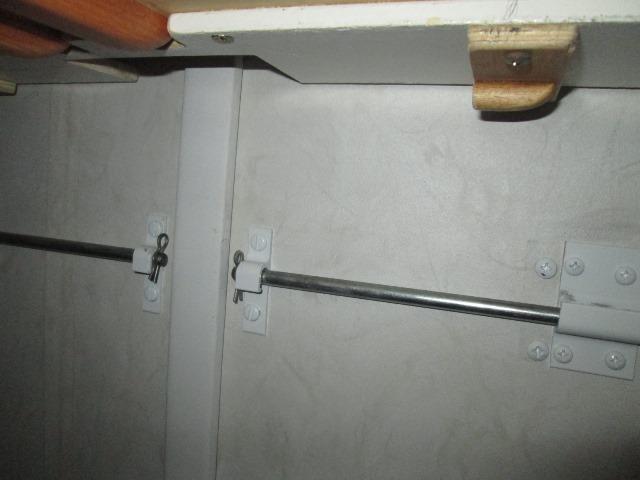
Pinned.
Functional, not the best looking mod but it'll be nice in use. With the addition of under table shelf we now have a place to store laptops etc. The added 110v shore/inverter split receptacle and inverter remote switches to right side of table allows AC access from either side of table, and now 12v outlets and/or 5v USB ports for charging without using inverter.
Well except my laptop. It requires 110V for its charger. I've located a charger that will charge at the needed 19v/4.7 amp and uses either 110v or 12v. It also has a 2.1a USB port. I don't know (doubtful) that bucking up 12v to charge at 19v will be more efficient than running the inverter but it will give me the option to charge off 110v or direct off the 12v. Round-toit Done!
We will be adding couple of USB ports somewhere in cabover. Will be pretty simple as there are several locations with cabinets that flush mount panels can be used by just cutting hole. There is also accessible 12v power that could be used. Though I'm pretty sure I'll run new wire and add to the existing, separate USB circuit. Which reminds me, need to relabel the fuse panel on converter.
On to part 4 Semi hardmount AC/DC charger for laptop
back Part 2, Add 110v Receptacle/Inverter remote switch
back Part 1, addition of under table shelf that started all this
Back to Ourelkhorn Camper Modifications page